Match Game
Andrew Wilson, Editor
Large-format CCD and CMOS area-array and linear sensors are now being incorporated into the latest cameras for machine-vision and image-processing applications. In developing cameras based on these imagers, engineers must carefully select the appropriate lenses to maximize the performance of their camera systems.
Indeed, some of the latest developments in large format imagers that include 16k × 1 linear and 50-Mpixel arrays are forcing optics manufacturers to rethink current lens-mount standards. For the system integrator, this promises to ease the task of matching the correct lens to a camera system. However, before any lens choice can be made, system integrators must understand exactly the application in which the lens/camera combination will be used.
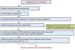
“While many developers will understand the nature of the product that is to be inspected,” says Stuart Singer, vice president of Schneider Optics, “they may not realize that choosing the correct lens entails more than specifying the field of view [FOV] and the size of the imager used in their camera system.” However, by following a series of relatively straightforward steps, this process can be simplified (see Fig. 1).
null
Optical magnification
In determining the correct lens for any specific application, this begins by determining the optical magnification of the lens. To calculate this, the developer must know the FOV of the object to be imaged, the size of the smallest defect to be resolved, the size of the pixels used in the imager, and how many pixels are needed to resolve this object. For example, if an object of 50 mm is to be imaged with a 75 × 50-mm rectangular CMOS or CCD imager, and the image fills the complete area of the imager, the magnification of the lens will be the FOV/image height or 50/50 = 1x.
Although this distance is specified for C, CS, and F lens mounts, there is not a standard available that describes the distances for the M39, 42, M58, and M72 lens mounts, which are more commonly used with cameras that incorporate large-format imagers. Thus, to calculate the focal length of a lens for such cameras, the system developer should consult the mechanical engineering data provided by each camera vendor.
According to Nyquist criteria, the smallest image that can be resolved will be approximately twice the size of the pixels used in the imager. For example, if the pixels used are 10 × 10 μm, the smallest measurement at a 1:1 magnification will be 20 μm. However, if the 50-mm object is farther from the image sensor, the image will need to be magnified to fill the image area of the sensor. Despite this increase in magnification, the smallest resolvable measurement will still remain 20 μm if the same camera is deployed.
In practice, of course, defects using a minimum of 3–5-pixel dimensions are usually required. Similarly, if an object is closer to the image sensor, it may need to be demagnified. These cases often occur in document-scanning inspection systems, for example, where the developer may wish to scan envelopes or labels on packages at 256 dots/inch (dpi) resolution. In these cases, each dot will measure 0.099 mm.
If an image sensor with a pixel size of 13 μm (or 0.013 mm) is used to image the packages, then a 0.013/0.099 or 7.6x demagnification lens is required to properly image the objects. Although understanding the magnification required to image an object is an important first step in determining a lens, this figure alone is not sufficient.
Working distance
For the system integrator, the working distance of the object from the front principle plane of the lens will determine the lens focal length. This focal length can be calculated by a simple equation available online at www.giangrandi.ch/optics/lenses/focalcalc.html that relates the distance of the object from the front principle plane of the lens to the distance between the image sensor and the rear principle plane of the lens, a distance that varies somewhat depending on which camera is used.
Although this distance is specified for C, CS, and F lens mounts, there is not a standard available that describes the distances for the M39, 42, M58, and M72 lens mounts, which are more commonly used with cameras that incorporate large-format imagers. Thus, to calculate the focal length of a lens for such cameras, the system developer should consult the mechanical engineering data provided by each camera vendor.
Once magnification and focal length are defined, a lens choice can be made by determining which available lenses can fully cover the image height of the camera’s image sensor. In considering this, developers must also understand whether the performance of the lens is commensurate with the sensor pixel size or the required resolution of the object being examined.
Achievable resolution
Indeed, to understand how lenses can limit the performance of an imaging system, it is necessary to grasp the physics behind factors such as diffraction, lens aperture, focal length, and the wavelength of light (see “Matching Lenses and Sensors,” Vision Systems Design, March 2009). One of the most useful benchmarks for describing lens performance and thus image quality is the modulation transfer function.
As Stuart Singer and Greg Hollows of Edmund Optics point out in “Specifying lenses for megapixel cameras” (Vision Systems Design, November 2009), to produce an MTF graph requires imaging a target whose intensity varies sinusoidally in space. The resulting graph of contrast against spatial frequency then shows the contrast at any given spatial frequency (or MTF) from 0 to 100%. At the cut-off frequency of the lens, the contrast in the sinusoidal image will be too small to detect.
A camera using an imager with 3.45-μm pixels, for example, is capable of resolving 1000/(2 × 3.45) or 145 lp/mm. If the cut-off frequency of the lens is less than 145 lp/mm, then the lens will not be able to resolve such detail. In considering the MTF, the effects of aperture and working distance also play a role in determining the performance of a lens (see http://photo.net/learn/optics/mtf/).
When all these factors are taken into account, the system developer must also consider the size of the imager used in the camera since it will directly affect the type of lens mount used by the camera vendor.
Standard mounts
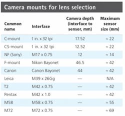
In most of today’s machine-vision cameras, Canon bayonet mount, C-mount screw thread, and F-mount bayonet thread versions are used to support maximum sensor sizes of 22 mm and 42 mm, respectively (see table).
“Standard Nikon and Canon lenses are relatively high quality and low cost as they were developed for the large-volume consumer photography market,” says Kerry Van Iseghem of Imaging Solutions Group. For example, in the company’s latest Kodak 16-Mpixel CCD design, ISG uses a Canon EF lens mount and a standard F-mount on its LW-PE-2048, 2k × 1, FireWire linescan camera.
“Many times sensor formats are smaller than the 35-mm mounts used, and in such cases, this works in the customer’s favor since the center of the lens produces a better MTF. Using a 1-in. or a 2/3-in. format lens for a sensor with a 1/2-in. format results in very little distortion when the sensor is located at the center of the lens and not the edges,” Van Iseghem says.
Indeed, one of the benefits of using such standard lens mounts is that the lens interface (be it thread or bayonet), the flange focal distance (the distance between the metal ring on the camera and the rear of the lens), and the maximum sensor size that can be supported are standardized.
“However,” warns Schneider’s Singer, “standard Nikon and Canon autofocus lenses are not powered by the cameras used in machine-vision applications, but these lenses do obtain power when they are coupled to Canon and Nikon consumer cameras. When these lenses are not receiving power, focus and iris settings can drift over time, and so the developer must be aware that critical calibration could be lost or changed.”
Large-format imagers
For designers of cameras with larger imagers, other lens mounts based on standard optical filter threads are most often used. While these specify the maximum diameter of the sensor that can be supported and the number of threads per inch used in the lens mount, they do not standardize a flange focal distance. Lens mounts such as M58 and M72 that support sensor sizes of 55 mm and 69 mm, respectively, support thread pitch distances of 0.75 threads per millimeter (tpmm).
In the design of its Osprey linescan camera, for example, Fairchild Imaging mounts its 4k × 1, 13 × 13-μm imager in a M58 × 0.75 base lens thread. For its Sprint 8k × 1, 82-mm, 10 × 10-μm linescan imager, Basler Vision Technologies has used a V92 lens mount that supports a maximum sensor size of approximately 89 mm. For its M40.5 × 0.5 AVIIVA UM8 CL 12 k, e2v recommends the use of Schneider Kreuznach Makro-Symmar 5.6/120 lenses since they have been designed specifically for small-pixel sensors, such as the 5-µm-square embedded in the AVIIVA UM8 (see Fig. 2).
In these and other large-format lens mount specifications, no flange focal distance is specified. Without a standard, it is more difficult to specify the focal length of a lens for these cameras since each camera vendor may use a different flange focal distance.
“In fact,” says Schneider’s Singer, “for cameras that use imagers greater than 42 mm, it’s like the Wild West of optical design with every manufacturer developing standards of their own.” Luckily, many manufacturers offer lenses with threads greater than 1 in. to accommodate these nonstandard mounts.
Where the difference in flange focal distance becomes so great between different camera models, either the focus mount of the lens can be removed or mechanical lens extensions added to increase or decrease the minimum focal distance of the lens. In both cases, image quality will be affected.
Luckily, for system integrators, this nightmare of multiple large-format mounts is about to end. Lens mount meetings originated by the Japan Industrial Imaging Association and endorsed by the Automated Imaging Association and the European Machine Vision Association aim to develop revised standards for these large-format imagers.
The organizations plan to standardize existing specifications such as the M58 mounts and others to provide standard flange focal distances and how coplanar each image sensor is with respect to the face of the camera. To support future high-resolution imagers now under development, the standard will also specify an M105 × 1 tpmm lens mount to support 16k × 1 imagers that are larger than 100 mm. Expected to be finalized next year, this standard will provide large-format-sensor vendors and their customers with a specification that will ease the task of specifying lenses for cameras.
Acknowledgment
The author would like to thank Stuart Singer, vice president of Schneider Optics, for his invaluable help in the preparation of this article.
Company Info
Automated Imaging Association, Ann Arbor, MI, USA www.machinevisiononline.org
Basler Vision Technologies
Ahrensburg, Germany
www.baslerweb.com
e2v, Chelmsford, UK
www.e2v.com
Edmund Optics, Barrington, NJ, USA
www.edmundoptics.com
European Machine Vision Association
Frankfurt am Main, Germany
www.emva.org
Fairchild Imaging
Milpitas, CA, USA
www.fairchildimaging.com
Imaging Solutions Group
Rochester, NY, USA
www.isgchips.com
Japan Industrial Imaging Association, Tokyo, Japan
www.jiia.org
Schneider Optics
Hauppauge, NY, USA
www.schneideroptics.com
