Capturing the Moment
Andrew Wilson, Editor
Exploding balloons, crash test dummies barreling into walls, and hummingbirds pollinating flowers are just some of the many images used by high-speed camera vendors to promote their products. While such images are impressive and represent different niche applications where the cameras are deployed, they rarely highlight the industrial and scientific applications for which these cameras are being used. In troubleshooting high-speed production lines, for example, cameras can be used to capture single or sequences of events, allowing the operator to analyze any mechanical faults that may be occurring.
In choosing a high-speed camera for a specific application—whether it is for factory automation, medical research, or destructive testing—it is often assumed that a high-speed camera must capture a sequence of events at high speed. However, this is not always the case. Should the duration of the event be understood, then a lower-cost CCD- or CMOS-based camera may be all that is required. Illustrative applications include capturing images of roller coaster passengers as they hurtle down a slope at high speed.
Although factors that affect the quality of an image captured at high speed include scene luminance, aperture size (f-number, f/#), shutter speed, and field of view, a simple calculation can determine the approximate shutter speed needed for such an application. Assuming that the roller coaster is moving at 60 mph, or approximately 27 m/s, and a 1k × 1k pixel camera is placed to capture a 1-m field of view (FOV) of the coaster as it passes, then during one second the carriage will have passed completely by the camera.
Stop motion
To stop the motion of such an image, a triggered fast exposure time can be used. To calculate how fast this exposure must be, the distance in pixels that the car moves across the FOV of the camera must be known. Imperx’s IPX1M48-G camera, for example, uses a Kodak KAI-1020 imager approximately 0.3 in.2 (or 7.6 mm) that features a CCD array of 1000 × 1000 7.4-μm pixels, and a range of shutter speeds from 1/30 to 1/50,000 s.
Choosing a shutter speed of 1/1000 s, for example, the roller coaster will travel approximately 27 × 1/1000 or 27 mm across the FOV after the camera is triggered. At the camera’s image plane, the distance the image of the coaster travels will be approximately (27 mm/1000 mm) × 7.6 = 0.2 mm (or 200 µm).
From these calculations, it can be seen that to stop motion, an exposure time of approximately 30 times faster or 1/30,000 s will be required to capture an image with pixel accuracy. With the triggering capability, well-understood events can easily be captured by off-the shelf cameras such as Imperx’s IPX1M48-G. However, as Nathan Cohen of Imperx points out, the camera can also be used in other modes.
In those modes, cameras may be limited in their data rate—the number of images that can be captured within a given period. For example, although the Imperx camera can be set to 1/50000 s (20 μs), the frame rate is 48 frames/s in the free running mode. For particle velocity measurements, the camera can also be used in a double triggering mode where the first exposure is 1 ms and the second exposure can be as short as 10 ms, with a 5-ms delay in between exposures.
Short shutter times, however, do not paint a realistic picture of how many high-speed cameras are used in applications where the timing of an event is unknown, for example, troubleshooting high-speed production lines in which several series of images must be captured at high speed. Here, cameras must exhibit high shutter speeds and high frame rates.
Data rates
To accomplish these frame rates, high-speed camera vendors use a number of different methods that include the use of high-speed CCD or CMOS image sensors, buffering a series of captured images in on-board memory, compressing the image data after it is captured, and using high-speed digital interfaces to transfer captured image data to the host PC. Here again, the choice of which camera to use is highly application specific, depending on the shutter speed required and the length of time that an image sequence must be captured.
In many of these types of cameras, region-of-interest (ROI) windowing is used to reduce the number of pixels that are captured while at the same time increasing the number of frames per second. In troubleshooting a machine-vision application, it may be necessary to capture and analyze a series of high-speed events to determine how an individual production process is occurring. In the roller coaster application for example, at 60 mph or 88 ft/s, the roller coaster will move 0.8 in. across the FOV of the camera in 1/1000 s, so that a frame rate of approximately 1000 frames/s will be required to capture every person on the ride.
However, to attain pixel-accurate images, a shutter speed of 1/30,000 s will still be required to capture a series of images with pixel resolution. The series of images will then represent snapshots of the sequence of events at distances of 0.8 in. apart.
To obtain the images, vendors such as Photron and Vision Research offer cameras that allow the user to configure the camera at various frame rates, image sensor sizes, and shutter speeds. Using a 1024 × 1024-pixel image sensor, the Fastcam SA5 from Photron, for example, can run at frames rates as fast as 7500 frames/s at megapixel resolution and 25,000 frames/s when the sensor is operated in 512 × 512-pixel windowing mode (see Fig. 1).
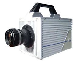
Since the camera’s global electronic shutter can be set as low as 368 ns, it can be used to capture transient events at high frame rates. Like the Imperx IPX1M48-G CCD, the Fastcam SA5 also features an inter-frame time of 1 ms, making it useful for particle image velocimetry (PIV) measurement.
Bright lights, big pixels
With such high exposure rates and frame times, the amount and direction of light used to illuminate a high-speed scene can be a critical factor in many applications. “The amount of light needed, the aperture of the lens, the shutter speed, and frame rate of the imaging system all play a critical role in determining whether a high-speed camera can be used in a specific application,” says Grant Reig, product manager with Olympus NDT.
As the shutter speed doubles, the effective amount of light reaching the image sensor will be halved. Thus, a high-speed camera running at a shutter speed of 1/1000 s will require 16 times the amount of light to illuminate the scene as a camera running at a shutter speed of 1/60 s.
To overcome this, fast lenses can be used to allow high exposure rates while at the same time increasing the amount of light reaching the sensor. For example, by using a lens with an aperture of f/2, images can be taken in one-quarter of the time needed to expose the same image with a lens featuring an aperture of f/4.
However, this is not the only method by which camera vendors are increasing the sensitivity of their cameras. Unlike consumer-based cameras where pixels as small as 2 × 2 μm are becoming the norm, high-speed camera vendors are using bigger pixels to increase the fill factor and the quantum efficiency of the sensors used in their cameras.
PCO Imaging, for example, uses pixels of 11 × 11 μm in the design of its pco.dimax, a 2016 × 2016-pixel CMOS-based camera that can operate at speeds as fast as 1100 frames/s at full resolution and with exposure times from 2 ms to 1 s. And, in the design of its latest Y4Lite, Integrated Design Tools uses a pin-photodiode, 1024 × 1024-pixel array with pixel sizes of 13.8 μm offering a frame rate at maximum resolution of 4000 frames/s.
In some cases, however, even high-speed lenses and imagers with large fill factors are insufficient to capture the required amount of light need for a specific application. In spectroscopy applications, for example, cameras such as those from Cordin use gated image intensifiers to capture sequences of images that occur as fast as 5 ns apart. In choosing a high-speed camera for a specific application, shutter speed, frame rate, and which types of imager are used are important in determining the quality of the captured image.
Memory on-board
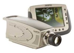
Of similar importance is how much on-board memory is required to capture a series of events and which type of PC interface the camera supports. For example, in the design of the Olympus i-Speed 3, the designers have incorporated a 1280 × 1024-pixel imager that captures full resolution events at 2000 frames/s and can achieve speeds of up to 150,000 frames/s by windowing the CMOS sensor (see Fig. 2). With a maximum-on-board memory of 16 Gbytes, 0.9 s at 2000 frames/s or up to 32 s at 150,000 frames/s of an image sequence can be stored.
The i-Speed 3 uses a Gigabit Ethernet interface that can transfer data between the camera and PC at speeds of 1 Gbit/s. Since the camera stores image sequences at the rate of 2 Gbytes/s at full resolution running at 2000 frames/s, image data sequences must first be stored in on-board memory before they can be transferred at the slower Gigabit Ethernet rate to the host PC.
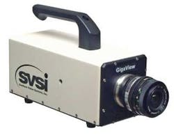
High-speed semiconductor memory is not the only option that camera designers can use to store image data. Although slower, image data can be streamed to on-board hard drives, an approach taken by Southern Vision Systems Inc. (SVSI) in the design of its GigaView camera (see Fig. 3). In operation, the camera can record 1280 × 720-pixel video at 750 frames/s to memory for 30 s when troubleshooting machinery, VGA 640 × 480-pixel video at 250 frames/s to disk for eight hours for monitoring and surveillance, or both at the same time.
Like the GigaView, the InLine camera from Fastec Imaging also features a Gigabit Ethernet interface to transfer image sequences to a host computer. With a 640 × 480-pixel color CMOS imager, the camera can be used to capture 4.4 s of image data at a recording speed of 250 frames/s. Captured images can then be transferred over the Gigabit Ethernet interface to a host PC for post processing.
Multiple cameras
Although most of today’s high-speed cameras use a single CCD or CMOS image sensor to capture images, other approaches can be used. While at Stanford University, Neel Joshi, now with Microsoft Research, for example, developed a system for capturing images consisting of thousands of frames per second using a dense array of inexpensive 30-frame/s CMOS image sensors.
In operation, the system captures and compresses data from many cameras in parallel, allowing the camera to stream images for minutes while eliminating the need for any triggers. In the design of the system, Joshi and his colleagues built an array of 52 cameras using 640 × 480-pixel Omnivision OV8610 sensors running at 30 frames/s.
With on-board MPEG compression and a FireWire interface, the effective frame rate of the complete camera system is 52 × 30 = 1560 frames/s. To remove the rolling shutter distortion associated with the Omnivision sensor, each of the camera triggers are evenly staggered, so at any time they are imaging different regions of the object plane.
Instead of interleaving the aligned images, scan lines captured at the same time by different cameras are stacked into one image. Using on-board MPEG compression, the data rate from the complete camera system is reduced to 26 Mbytes/s, allowing data to be streamed to a PC at 1560 frames/s.
While the design of camera systems like this have yet to be commercialized, companies such as Point Grey Research recently demonstrated a prototype of a similar—albeit slower—multiple camera concept, known as a lightfield camera that allows the user to select the depth of field of an image after it is taken or render novel 3-D views of a scene (see “Speeding up the bus,” Vision Systems Design, January 2008). Using a 5 × 5-pixel array of low-cost MT9V022 wide-VGA CMOS sensors from Aptina Imaging and a PCI Express 1.1 interface, the camera can transfer 640 × 480-pixel images from all 25 imagers directly to the host computer’s main memory at rates of 25 frames/s.
Carefully considering the application for a high-speed camera will dictate the type of camera that must be used. Whether those applications demand high shutter speeds, fast frame rates, imaging in low-light conditions, or recording hours of image sequences may narrow the potential cameras to just a few models. Luckily, unlike the general-purpose machine-vision camera market, there are relatively few companies that produce high-frame-rate cameras with fast shutter speeds, narrowing the choices of which type of camera is best for any specific application.
Image analysis accelerates understanding of high-speed events
While high-speed cameras certainly produce dramatic slow-motion videos, scientific users are primarily interested in extracting and quantifying the motion of their fast-moving events (motion analysis). Due to the speed of image capture, such analyses cannot be performed in real time but instead must be performed off-line.
“Users typically rely on motion-analysis software to help with the data extraction and presentation,” says Peter Carellas, president of Xcitex. “Users of video cameras today study everything from speeds and distances to complex mechanical motions and particle migrations. We have the benefit of using time as a measurement variable, so the image-processing and measurement tools can include the ability to track and analyze objects over time using a variety of interesting methods.”
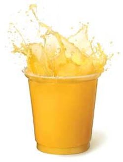
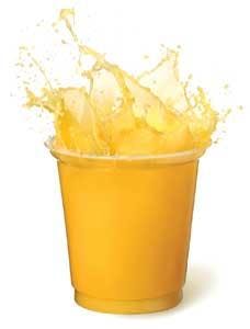
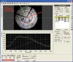
In the case of combustion flame analysis, for example, the rate of combustion can be measured by analyzing the rate at which the flame front propagates across the image (see Fig. 1). In such cases, all that is required is to measure the difference in grayscale of pixels across one dimension of the image. By setting a one-dimensional line tool across the image and calculating the grayscale difference across this line, a series of points will be generated throughout the frames. Because the camera’s frame rate is known and the distance between these points can be automatically measured, the combustion rate can be calculated.
Perhaps a more dramatic example of the benefits of motion analysis software is that of studying an airbag deployment (see Fig. 2). “In these applications,” says Jesse Hong, director of analytical products with Xcitex, “blob-analysis techniques can be used to identify a specific region (in this case, an airbag) within an image. In the blob-analysis algorithm used in the ProAnalyst package, individual pixels within the image are classified by their value and regions of adjacent pixels with the same value are considered part of the same blob.
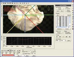
“Once these blobs are classified, features such as area, perimeter, and center of gravity (COG) can be calculated and displayed. In airbag deployment analysis, such tools can automatically generate the perimeter of the airbag from a sequence of images. By combining this tool with a one-dimensional measurement tool, the expansion velocity in any direction can be automatically generated.”
Such analysis tools have recently become pervasive in medical research applications. At present, researchers at Mass General Hospital in Boston are using ProAnalyst software to study the motion of vocal cords from a series of high-speed images taken with a high-speed endoscopy camera.
Engineers also employ motion-analysis tools in vibration testing environments to assess lifecycle failure or fatigue areas. “In such applications,” says Carellas, “it is often necessary to algorithmically remove the background motion of the vibration platform or stress tester before actually tracking specific product features.” Once this is accomplished, only the motion of the part will be seen—whether the object is a cell phone or a motorcycle brake during testing—allowing engineers to more clearly visualize any fault that may have caused the problem.
Company Info
Aptina Imaging, San Jose, CA, USA
www.aptinaimaging.com
Cordin Scientific Imaging
Salt Lake City, UT, USA
www.cordin.com
Fastec Imaging
San Diego, CA, USA
www.fast-vision.com
Imperx, Boca Raton, FL, USA
www.imperx.com
Integrated Design Tools
Tallahassee, FL, USA
www.idtvision.com
Kodak Image Sensor Solutions, Rochester, NY, USA
www.kodak.com
NAC Image Technology
Simi Valley, CA, USA
www.nacinc.com
Olympus NDT, Waltham, MA, USA
www.olympus-ims.com
Omnivision, Santa Clara, CA, USA
www.ovt.com
PCO Imaging, Kelheim, Germany
www.pco.de
Photron, San Diego, CA, USA
www.photron.com
Point Grey Research
Richmond, BC, Canada
www.ptgrey.com
Southern Vision Systems
Madison, AL, USA
www.southernvisionsystems.com
Vision Research, Wayne, NJ, USA
www.visionresearch.com
Xcitex, Cambridge, MA, USA;
www.xcitex.com