Model World
Andy Wilson, Editor
“For many years,” says Matthias Voigt, president of SensorDesk, “mechanical, optical, and electrical design engineers have used engineering design software packages in the design and optimization of their products. With these packages engineers can model the 3-D system geometry, simulate and optimize system characteristics, and document or collaborate easily.”
Often, digital simulations help identify design conflicts before engineers get involved with hardware, and developers can showcase proposed systems to colleges and potential customers very early with little upfront investment. “Because of this,” says Voigt, “many new products, modern machines, or even factories are first specified and optimized in a virtual or digital environment, where designers can identify, review, and change specifications easily.

“While machine-vision system designers can use different engineering software packages to model the mechanical, optical, or lighting aspects of their systems, there has been as yet no integrated software package that allows the vision system itself to be modeled, simulated, and characterized sufficiently as a virtual system,” says Voigt “although such systems were described in the literature as early as 1991. Slow real-time graphics have prevented correct interactive simulations until recently.”
CAD for machine vision
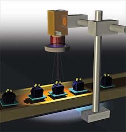
With DirectX 9 available on many computers, SensorDesk is introducing the Vision System Designer 1.0 software, specifically for planning, simulation, and analysis of machine-vision and imaging applications. This will allow vision system designers to start their designs in a virtual 3-D environment by modeling and combining various lenses, cameras, and light sources.
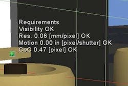
By modeling the vision system and integrating a model of the product to be imaged, developers are able to view simulated images of the objects as seen by the sensor. The software can also calculate various performance characteristics, which show, for example, at different points the resolution, motion blur, or perspective distortions (see Fig. 1). In contrast to a laboratory setup, the Vision System Designer software can automatically visualize annotations, such as the 3-D-bounding box of the view volume that combines field of view and depth of field (see Fig. 2).
null
Engineers can also enter vision system characteristics as requirements and optimize the system until the associated markers placed at the inspected object turn from red to green, which means that the requirements are fulfilled. Once images are simulated, these images can be exported and used with off-the-shelf image processing or machine-vision software, although there are some limitations. “In this way,” says Voigt, “the system developer will be able to validate the design of the vision system before they even order hardware, and they can later compare this with the installation.”
Just as traditional CAD packages allow a variety of systems to be evaluated and optimized before they are built, Vision System Designer will perform these functions, support component selection, and provide developers with a semirealistic system user experience.
“The semirealistic user experience also has great potential,” says Voigt, “if used in marketing, training, maintenance, and service. For example, interactive 3-D simulations can easily show how specific components are used in different applications.”
While the concept behind Vision System Designer is elegant, the task of developing this type of software is not trivial. As many system designers know, there are numerous variations and combinations of lenses, cameras, and lights in different application contexts, and performance characteristics often depend on how these components work together. In addition, developing interactive 3-D software has its own challenges.
Characterizing cameras and lenses
To effectively develop a CAD model of a machine-vision system also requires analyzing how each camera and lens combination will perform. “A camera model combines three aspects,” says Voigt, “the camera geometry, interfaces, and internal camera characteristics related to the image formation.” Most camera vendors include specifications in their data sheet such as pixel and detector size, lens mounting, frame rates, detector types, and data interfaces. These basic specifications already allow the simulation of geometric image-formation characteristics.
The radiometric simulation is more complicated. Some camera vendors have adopted the European Machine Vision Association (EMVA) 1288 standard, which provides an accurate measure of the absolute quantum efficiency, signal-to-noise ratio (SNR), nonuniformity, and nonlinearity of the camera. Where possible, these specifications will be incorporated into the Vision System Designer.
In many cases, however, camera vendors have not yet characterized their cameras to the 1288 specification. Until then, the simulation is founded on a basic photodetector response curve and SNRs that enable the estimation of lighting levels and contrast for a given integration time, pixel size, lens aperture, focal length, and surface luminance.
Of course, the choice of lens will also affect how the cameras and lighting combinations operate in a given system. Just as camera vendors often do not provide full specifications about the performance of their products, lens manufacturers can be equally as reticent.
“To overcome this,” says Voigt, “a thick-lens model of the lens can be used.” While a thin-lens model treats a lens as a plane with zero thickness, the thick-lens model divides the thin-lens plane into two planes that contain the entrance and the exit pupils of the lens. This model is usually used by optical engineers and does not reveal all lens details.
“The location of the principal planes in the thick-lens model along with the aperture and the focal length can be used to effectively model a lens since the focal length determines the angle of view and the size of the image relative to that of the object, while the aperture limits the brightness of the image,” says Voigt.
The program can also work directly with tabular surface descriptions of lenses in case that information is available and then perform 3-D ray tracing and generate sensor images. Some models of common lens and camera types are already available in the Vision System Designer software’s database and allow an easy start.
Characterizing lighting
The correct simulation of lighting is computationally expensive and requires detailed modeling of material surface characteristics. “Initially the lighting problem was off the table because of the complexity involved,” says Voigt, “but you do not need a complete simulation to address some common problems. You can get away with a much simpler model if you need to find out the lighting level, physical size of the light, and if there are specular reflections or shadow casts at the object of interest that can interfere with your imaging algorithm.”
To characterize different light sources, optical design engineers could model the individual spatial luminance distribution of each illumination element such as an LED and the position and number that are used in each individual product. Although this would be time consuming, it would result in an accurate model of the lighting element. “More suitable for real-time simulations, however,” says Voigt, “is the light or luminance field generated by the entire illumination source at a specific distance and angle from the part under test.
“Of the many different lighting products available, integrated illumination models include spotlights, linear lights, dome lights, collimated lights, structured lights, and backlights. While it is important to consider specular reflections when using spotlights, it is less of a concern with dome lights or cloudy day lights that create minimal glare due to a diffuse uniform light field,” says Voigt.
By characterizing this light field for a number of different lighting products, a model of how the light is reflected from the product to be examined can be computed. “Although the current real-time implementation does not follow second-order reflections, regions with direct specular reflections can be identified.”
To accommodate these different lighting models, Voigt and his colleagues plan to further develop specific light field models for commercially available products and incorporate them into a database within the Vision System Designer package.
Modeling systems
Once lenses, cameras, and lighting are modeled, developers will be able to use the software to develop a virtual operating CAD model of their machine-vision system. To do so, they can describe the application context—for example, the machine geometry—by importing existing models using the Stereolithography (.stl) and 3D Studio (.3ds) file formats. STL files describe the object geometry as a triangulated surface and can be exported by many other software packages. 3ds files also contain surface texture and color information.
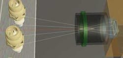
To model, for example, how a machine-vision system could be used to inspect the distance between the spark gap of a spark plug, developers could first import existing models of the production system or build a coarse model in Vision System Designer. Then, by importing a CAD model of the spark plug into the system, developers could position and animate the product as it would appear on the production line (see Fig. 3).
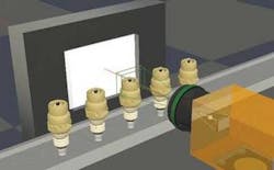
After integrating and specifying a CAD model of the application domain, developers would use Vision System Designer to choose the type of cameras, optics, and lighting used to image the device. In a virtual environment, this hardware could then be placed exactly as it would appear in the finished system.
“Once individual components have been chosen,” says Voigt, “the system is able to show simulated images of the part as it would be seen by the imaging system (see Fig. 4). This virtual image data can then be exported into off-the-shelf machine-vision packages, for example, to estimate computation time requirements for the image analysis.”

The Vision System Designer software represents a major step forward for developers of machine-vision systems. According to Voigt, the company will offer two versions of the software, one of which will be freely available from the company’s web site for potential customers to evaluate the software before purchasing. Pricing is expected to be $2500 with OEM discounts for large end users.
features, advantages, benefits
Engineering design software is established across many industries, reducing time to market and enhancing development. CAD models are also used outside of engineering during product lifecycle management. For example, CAD models are used to automatically generate part lists for purchasing and logistics. Rendered CAD models provide drawings for assembly, documentation, and marketing, and find use in manufacturing, maintenance, validation, and quality control.
“Although CAD software packages have been available for decades,” says Matthias Voigt, president of SensorDesk, “they are limited in their ability to model and characterize machine-vision systems. Unfortunately, this limits how machine-vision systems are considered during many decisions in a virtual design process of a new machine.
“And while many engineers start off in a virtual environment with their engineering software, vision system engineers will often wait for hardware and then work out many details under more time pressure. If new systems are not tested in the lab, then there is a higher project risk at installation.”
Company Info
SensorDesk
Newark, NJ, USA
www.sensordesk.com