Assembly Required
Winn Hardin, Contributing Editor
Aircraft engines are comprised of thousands of individual components such as screws, bolts, flanges, wires, and tubes. Because of the engines’ complexity, final assembly is done manually over many days by mechanics in specialized 14 × 14-ft work cells. To assist in their work, computers connected to the plant network guide mechanics through the assembly process. As one phase is completed, the computer asks the mechanics to verify placement of each part within that step, but even the most highly trained mechanic can overlook one among dozens of bolts.
While missing parts are caught long before the plane takes its maiden voyage, during the integration of the engine into the aircraft body, the cost to rework the engine is significant. Mechanics must be sent from the assembly plant to the customer location, sometimes spending hours or days reworking the engine to install a missing part.
To assist mechanics at the engine assembly plant and provide an objective verification that all critical parts during each phase of the assembly have been installed correctly, one of the main US suppliers of aircraft engine assemblies turned to Aptúra Machine Vision Solutions to create a machine-vision system that could identify hundreds of individual parts installed on the engine, ensure that they are installed correctly, and produce a verification report of the final assembly (see Fig. 1).
Aptúra developed large-area illumination sources that would not interfere with the working mechanics and installed eight Allied Vision Technologies FireWire cameras around the work cell with FireWire hubs to extend the cable length up to 40 ft or more back to the host PC. The Cognex VisionPro image-processing suite, running on the host PC, supplied the dozen algorithms necessary to locate and inspect the hundreds of individual parts.
Human lighting
Correct lighting is critical to success; however, when mechanics work in close proximity to the vision system, high-powered LED arrays, strobes, and arc lamps can be impaired or damaged if proper measures are not taken. Aptúra was clearly instructed by the engine manufacturer that the machine-vision system could not impede the mechanics during their inspection.
Consequently, the vision system designers needed to place lights and cameras along the walls of the work cell, and they would have to be strong enough to yield quality images from the cameras but not so bright as to hurt the workers’ eyes. The task was made more difficult because the engines are constructed from polished metals and stainless steel—highly reflective materials that can challenge the dynamic range and gain settings of industrial cameras and image-processing techniques.
Aptúra’s president David Dechow developed a large-area lighting system using fluorescent lights with high-speed ballasts and large diffusion plates measuring several feet on each side. “When we must use fluorescence for machine vision, the ballasts that drive the lights must be running at a high frequency [about 20 kHz] and not at the usual 60-Hz frequency,” explains Dechow.
He says, “At the lower speed, the lights pulse at a rate that can cause severe fluctuation in the amount of light that gets to the camera on a trigger-to-trigger basis. Some nonfluorescent light sources also exhibit this 60-Hz pulse. It’s best to always use lights intended for machine vision when applicable.” The diffusion plates and lights were hung above the workers, shining down on the engine in the middle of the work cell.
“Typically, we like to use high-intensity LEDs because of their longevity, low-heat output, and low-power consumption and associated benefits, but in this case, the customer had very specific limitations on the lighting system,” notes Dechow. “It turns out that adding the lights and the diffusion plates was good enough for the vision system and excellent for the operators. Using diffusion plates, we helped reduce the bright reflections and glare that the mechanics had to work around every day.”
Checks and balances
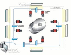
Once the lighting was in place, Dechow installed eight Marlin FireWire cameras from Allied Vision Technologies in a tree topology. Each camera connects to one of six FireWire hub/repeaters, which feed two PCI FireWire 400 boards, also from Allied Vision Technologies, installed in the host PC. FireWire 400 can transfer up to 400 Mbits/s, which was adequate for this off-line inspection process.
With eight cameras spaced evenly around the 14 × 14-ft work cell, only four cameras are within the 15-ft limitation. Therefore, Dechow installed two FireWire hubs/repeaters on opposite sides of the work cell. The remaining four FireWire cameras connect to the PC through the hub/repeaters (see Fig. 2).
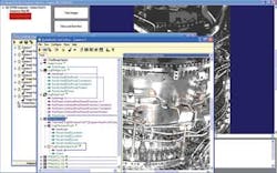
During operation, the mechanics’ team begins the day’s assembly task by turning on a nearby PC connected to the plant’s enterprise resource planning (ERP) software. This software tracks all engines and subcomponents, as well as providing step-by-step assembly instructions to the mechanics (see Fig. 3).
The mechanics are well trained in the assembly process, but the computer-assisted instructions inject an extra quality check into the assembly process. The vision system was designed to close the loop and verify that all critical assemblies for each phase of the engine build have been followed and correctly installed.
Because the mechanics were comfortable interfacing with the ERP system, adding an extra step to trigger the vision system was not a problem, Dechow says. However, once the system was installed, the customer discovered that verifying every single step in the assembly process was neither necessary nor effective. “The system was a cautionary tale to some extent because we designed the system to do exactly what the customer asked, and it worked,” notes Dechow. “Unfortunately, that was the downside, too.”
When triggered, the eight Marlin cameras each sent an image showing 1/8 of the circumference of the aircraft engine to the Cognex VisionPro image-processing software resident on the PC. “If you were looking at a hole and needed to verify that it went through a bracket to a certain depth, you’d use a measurement algorithm and edge detection,” says Dechow.
“On the other hand, some brackets had features that responded better to geometric pattern searches. Also, for each inspection step, the camera configuration would have to be changed to optimize the picture, so we had a hierarchy of configurations for a given step, using a variety of tools from edge detection to blob morphology or pattern matching, just to name a few. As you would expect, we had to develop a fairly complex frontend to handle the training and inspection routines,” he adds.
Complicating the matter, the customer wanted to be able to add new parts, edit part dimensions, and add new engine designs whenever a new engine was designed, so Aptúra designed the frontend to walk engineers through training the vision system to recognize each part and locate fiducial features that would allow the vision system to verify steps, such as that the right part was installed in the right place and to the correct depth.
Simplifying complex tasks
“It’s not that it was hard, but it was tedious,” explains Dechow. “That’s why the customer decided to scale back the inspection from every part to critical parts that would cause the biggest problems if they were overlooked or installed incorrectly.
“Many people intuitively yet incorrectly think that machine vision works by just taking a picture of something, storing that picture, then comparing subsequent pictures to the first one to see if something has changed. This is how our eyes and brain work—so it’s normal to assume that functionality,” he adds.
“While this kind of processing is occasionally used in very specific situations, this simply is not the way machine vision generally works. Machine vision processes discrete features by analyzing geometric structure or grayscale [intensity of pixels] content in isolated regions of interest of an image. Therefore, if one wants to see if a bracket is in a specific position, one must first compensate for movement of the scene due to process variations—usually by locating a known repeatable feature—and then applying tools to extract appropriate feature information in the target region to verify a part is present, or to gauge the position of the feature. All without confusing that target feature with something else in the background. Of course, the more complex the scene—like a jet engine—the more potentially complex the process.”
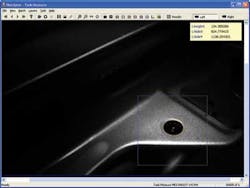
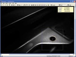
As mechanics finished a step in the assembly, they would trigger the vision system to collect its images and verify critical part location and installation. Parts that were missing or incorrectly installed are visually flagged by the system (see Fig. 4). The vision system will not proceed to the next step until the mechanics have corrected the problem or signed in and overridden the system with an explanation as to why (see Fig. 5). Pass/fail images were stored locally on the PC host, which was connected to the plant ERP network for easy access.
Company Info
Allied Vision Technologies
Stadtroda, Germany
www.alliedvisiontec.com
Aptúra Machine Vision Solutions
Lansing, MI, USA
www.aptura.com
Cognex
Natick, MA, USA
www.cognex.com


