Camera Connections
Numerous connectors, cables, and interfaces ease the task of interfacing Camera Link cameras to computers
Andrew Wilson, Editor
As the most well-established point-to-point interface in the machine-vision industry, theCamera Link standard has been incorporated on hundreds of cameras and frame grabber boards. First ratified in 2000 by the Automated Imaging Association (AIA), the 680-Mbyte/s standard has evolved in the last decade to incorporate a number of different extensions that feature smaller connectors and support for power. Extensions yet to be approved by the AIA also include support for higher and lower data rates using even smaller connectors.
For developers wishing to integrate Camera Link cameras into tight spaces, connectors and cable companies have responded accordingly, offering various connector types to simplify system integration. While speed, power, data rates, and connector concerns have been addressed by camera and frame grabber vendors alike, so too has the 10-m maximum cable length of the camera-computer interface. Originally, the maximum cable length advertised by the Camera Link Committee was 10 m. This was based on clock speed that originated from 33 to 40 MHz in Base mode. With the advent of Medium and Full mode along with clock speeds up to 85 MHz, very few cable manufacturers can reach more than 7-m lengths.
A number of cable companies and third-party suppliers offer repeaters either as part of the cable assemblies themselves or as standalone units. With these developments, a plethora of products are available to ease the task of interfacing Camera Link cameras to computers.
Camera Link standards
When initially developed, the Camera Link specification dictated the use of a 26-pin Mini-D Ribbon connector to carry data, control, and clocking information. Available from 3M, this 39.7 × 12.8-mm connector is used by camera and frame grabber companies to allow a single Base configuration Camera Link interface to transmit data at rates up to 255 Mbytes/s.
To implement the Medium and Full interface, however, requires two such cables, allowing respective bandwidths of 510 Mbytes/s and 680 Mbytes/s. With the introduction of smaller cameras and the need to interface to small form-factor add-in boards such as PC-104, the need emerged for a smaller pin-for-pin compatible connector. Honda developed a 26-pin Shrunk Delta Ribbon Connector (SDR) that is now offered by 3M as an SDR connector and by Honda as an HDR connector.
Realizing the need to support power over the Camera Link interface, a Power over Camera Link (PoCL) standard was then developed that redefined pins 1 and 26 of the Camera Link interface. Originally assigned to an inner shield, these pins are defined in PoCL as power lines that deliver up to 333 mA at 12 V or 400 mA at the lowest allowable 10 V.
By doing so, the original MDR-26 and SDR-26 connectors could still be used. However, this required cable manufacturers to redesign their products in order to reduce the effects of any power-generated noise. Camera and frame grabber manufacturers needed to re-engineer their products to incorporate a SafePower mode to eliminate the use of previous-generation unpowered cameras from shorting when powered from PoCL-enabled frame grabbers.
Having two different physical means to link Camera Link products is beneficial for those who may wish to mix and match camera and frame grabber products that use existing MDR-26 connectors with those that incorporate the smaller SDR-26 connector. Since these are both electrically compatible, cable manufacturers such as 3M, Components Express Inc. (CEI), and Intercon 1 offer cables that link both MDR-26 based products with those that incorporate both the SDR-26 connector. This allows both the original Camera Link standard and the PoCL standard to be supported with different connector types across a range of products.
A lighter version
While these developments have been blessed by the Camera Link committee, the need to reduce the size of this connector and further increase data rates has led some manufacturers to develop interfaces that stray from the original specification.
Last year, for example, the Japan Industrial Imaging Association proposed an interface calledPower over Camera Link Lite (PoCL-Lite) in an effort to reduce the camera connector size further. By redefining the PoCL standard using 14 pins, image data are transferred over just two differential line pairs, resulting in a maximum data transfer rate of 106 Mbytes/s when 85-MHz transceivers are employed.
Because PoCL-Lite is not electrically compatible with the PoCL-Base standard, new connectors and cables are needed to support camera-to-frame-grabber transfer (see Fig. 1). To support camera-to-computer connections using the PoCL-Lite standard, SDR-14 or HDR-14 connectors are employed. Measuring 20 × 5 mm, these connectors both reduce the bulk of cabling required and provide a smaller interface to manufacturers of very small cameras.
At VISION 2009 in Stuttgart, Oki Electric Cable showed tentative versions of a PoCL-Lite cable, the CL-SL-SS-PL-030 on the booth of the JIAA. Other such cables were also on show from 3M.
Despite the interest in the PoCL-Lite standard shown by many Japanese camera manufacturers such as CIS Americas and Hitachi Kokusai Electric America, there are few frame grabbers that support this standard, although Graphin Co. is expected to release a version of its x1 PCI Express board soon.
On one hand, this is surprising since, according to the company’s web site, Hitachi Kokusai Electric alone expects to ship 3000 of its PoCL-based cameras this year. On the other hand, the reluctance to adopt PoCL-Lite has probably hindered the development of such products in both the US and Europe.
Extending reach
While standards continue to emerge, cabling manufacturers and third-party suppliers are looking to extend the 10-m camera-to-computer limit set forth in the established standard. Just as system integrators can now choose from a number of different standards and yet-to-be standardized methods of linking Camera Link cameras, so too are there a number of means to extended this 10-m distance.
A number of companies have developed repeater units that can extend the distance of Camera Link well beyond 10 m at 85 MHz. In configurations like this, power must be delivered to the repeater placed at a 10-m distance from the camera, which may—in some robotics applications, for example—prove problematic.
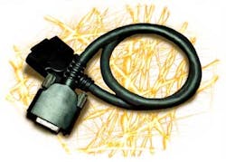
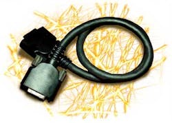
To alleviate this problem, CEI has developed products that utilize pre-emphasis and equalization within the cable so that a repeater is not needed (see Fig. 2).
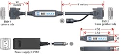
CEI’s Bit Maxx can be used to extend camera-to-computer distances to 30 m. Bit Maxx is offered in two versions that support Base and Full Camera Link modes. Bit Maxx-enabled cable requires an external 3.3-VDC power supply. However, the power is integrated at the connector closest to the frame grabber, alleviating the need for lengthy 10-m power supply cables used in repeater applictions. The cables can reach more than 25 m in Base mode at 85 MHz, 18 m in Full mode at 85 MHz, and more than 30 m at lower clock speeds.
Faster and smaller
While manufacturers continue to develop new cables and connectors based on the established Camera Link standard, the need to develop faster interfaces has emerged as a result of growing demand for a standard to support high-data rate CCD and CMOS cameras. Nowhere was this more evident than at VISION 2008, where Awaiba showed a 16k × 1-pixel imager and prototype camera configuration running at 1.6 GBytes/s, which required two Camera Link Full data interfaces using four Camera Link cables running in parallel.
To resolve bulky wiring problems, the Camera Link committee will soon endorse a new standard, Camera Link 2, which will be based on HSLINK from DALSA. The company has already established the interface in its Piranha HS 12k × 256-pixel TDI camera, which can transfer images at 1.2 Gpixels/s to a host PC using the company’s Xcelera-HS PX 8 frame grabber.
In theinitial HSLINK demonstration at VISION 2009, DALSA employed the SSF-8470 thumbscrew connector and the same cable used in InfiniBand, Fibre Channel, and 10GigE-CX4 standards. According to Mike Miethig of DALSA, the company has tested W.L. Gore, CEI HSLINK, and Hirakawa Hewtech 20-m cables with success, although only 15-m lengths are guaranteed.
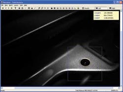
At The Vision Show 2010 in Boston, CEI also showed a proof-of-concept cable/connector combination that supported a 1x configuration of HSLINK (see Fig. 3). This consisted of a 3 × 5-mm, dual 50-Ω coax cable rated for 25 million flex cycles soldered to an SFF-8470 connector. According to Miethig, this connector will most likely be replaced by a smaller connector once the standard is released for 1x. The 300-Mbyte/s uplink and 300-Mbyte/s downlink speed of the 1x cable exceeded the 255-Mbyte/s downlink capability of Camera Link Base cable and, Miethig says, should support power over the cable and be less expensive to build.
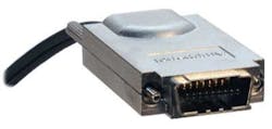
FIGURE 3. For the next generation of Camera Link interfaces, DALSA uses an SSF-8470 thumbscrew connector and the same cable used in InfiniBand, Fibre Channel, and 10GigE-CX4 standards. As a proof of concept, CEI has also developed a cable that couples this connector to a dual 50-Ω coax cable. (Courtesy of CEI)
Company Info
3M
St. Paul, MN, USA
solutions.3m.com
Automated Imaging Association
Ann Arbor, MI, USA
www.machinevisiononline.org
Awaiba
Madeira, Portugal
www.awaiba.com
CIS Americas
Bellevue, WA, USA
www.cis-americas.com
Components Express Inc.
Woodridge, IL, USA
www.componentsexpress.com
DALSA
Waterloo, ON, Canada
www.dalsa.com
Graphin Co.
Tokyo, Japan
www.g-in.co.jp/English
Hitachi Kokusai Electric America
Woodbury, NY, USA
www.hitachikokusai.us
Honda Connectors
Bannockburn, IL, USA
www.hondaconnectors.com
Intercon 1
Baxter, MN, USA
www.nortechsys.com/Intercon1
Japan Industrial Imaging Association
Tokyo, Japan
www.jiia.org
Oki Electric Cable
Kawasaki, Japan
www.okidensen.co.jp/en/
W.L. Gore
Landenberg, PA, USA
www.gore.com
Vision Systems Articles Archives