Riding the Rails
Andrew Wilson, Editor
High-speed trains traveling in excess of 300 kph use existing or modified railway networks that may be tens or even hundreds of years old. To ensure the safety of the tunnels, bridges, and underpasses that make up these rail networks, they must be inspected on a regular basis. In the past, inspections were performed visually, often during off-peak traffic hours to ensure the safety of the workers and to allow uninterrupted train services during peak periods.
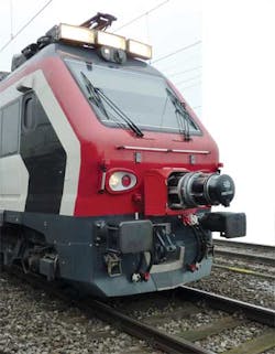
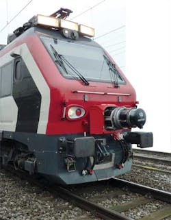
Despite these measures, inspections are still subject to human error and cannot be performed rapidly. The Mermec Group has developed an automated imaging system that allows inspections to be performed in real time at speeds greater than 300 kph (see Fig. 1).
Mounted to the front of a high-speed train, the T-SIGHT 5000 system performs an in-depth inspection and analysis of tunnels and clearance profiles on railways, capturing image data of bridges, underpasses, poles, walls, tree branches, and other obstacles that may hinder the safe transport of rail passengers and cargo.
Better still, once image data are captured, the system can visually recreate 3-D images of the railway infrastructure. This allows clearance measurements and surface conditions of features—such as possible cracks in tunnel walls—to be analyzed offline, eliminating the need for manual inspectors to walk the tracks and in turn speeding up data collection. Of course, collecting and computing the image data at such high speeds is no mean feat.
Time of flight
“In the past,” says Pietro Stama, marketing director at Mermec, “operators relied on laser-based time-of-flight (TOF) systems to perform clearance profile measurements of tunnels and other structures that may surround the track.” These systems perform 3-D scans of wide areas by vertically deflecting a laser using a rotating polygon and then rotating the optical head 360° to provide a horizontal data scan (see “Scanning Sensors,” Vision Systems Design, December 2010).
“While effective, these scanners are limited by their rotation speeds,” says Stama. “Thus, to detect any objects within the field of view of approximately 1 cm in diameter (as required by the Swiss Railway authority), these scanners must either be operated at a very high frequency or, alternatively, travel at relatively low speeds. Either way, the resolution obtained is often unacceptable,” he says.
To overcome these limitations, the T-SIGHT uses a more elegant approach to capture 3-D data. Because the system must simultaneously measure the clearance profile of the track and automatically evaluate the surface conditions of the tunnel walls, the complete optical system comprises two distinct but interrelated parts: a clearance profile measurement system and a tunnel inspection system.
Laser illumination
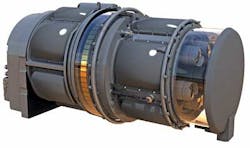
Before data can be captured from these systems, the field of view (FOV) surrounding the train track must first be properly illuminated. The T-SIGHT 5000 system uses an array of 60 multibeam laser diodes from Northrop Grumman that are mounted on the circumference of the system so it can perform equally well in any lighting conditions without interfering with the train operator’s view (see Fig. 2).
Each 810-nm 3R class laser consists of 46 laser emitters that are collimated using a combination of cylindrical and aspheric optics to generate a 360° line profile, which is maintained up to 10 m from the system. Both the clearance measurement subsystem and the tunnel inspection subsystem use this structured light to measure the profile and simultaneously capture high-resolution image data.
To build a 3-D profile of the inside of a tunnel, the reflected laser profile is first captured by a high-speed CMOS camera, then image data read are from the camera and the point cloud data are used to reconstruct a 3-D model of the part (see “Reading the Shapes,” Vision Systems Design, March 2008).
In the T-SIGHT 5000 system, five 1-Mpixel CMOS Camera Link cameras are mounted in front of five anamorphic mirrors custom-designed by Mermec. These mirrors deflect the impinging reflected laser light from the walls of the tunnel orthogonally into the camera lens, allowing a line profile from the complete 360° circumference of the FOV to be captured by the five cameras.
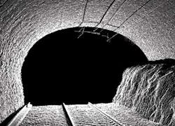
The image data are then transferred over the Camera Link interface to a Camera Link frame grabber that is situated in the cabin of the train. Here the individual line profiles are analyzed using a multicore CPU, the distance information computed, and a 3-D map of the tunnel wall recreated (see Fig. 3).
“Acquiring image data at 1000 gauge profiles per second, the azimuthal image resolution obtained can vary from 2–10 mm depending on the clearance distance, with a measurement uncertainty from 1–10 mm,” says Pasquale Antuofermo, head of new product development at Mermec.
Linescan cameras
Although this accuracy is good enough for clearance measurements, the second optical tunnel inspection system in the T-SIGHT 5000 is used to capture image data at a higher resolution so any cracks or objects within the tunnel can be more accurately analyzed.
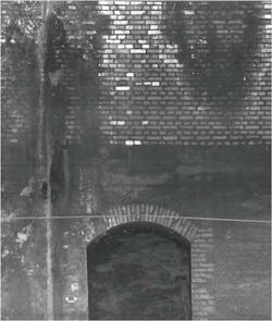
The system also employs five 4k × 1-pixel Piranha linescan cameras from DALSA that are mounted along the axis of the system. To capture linescan image data, five mirrors mounted at 45° in the optical axis capture the reflected light from the laser illumination. In this way, a complete 360° circumference of the FOV is captured. The data are transferred over the Camera Link interface to another multicore CPU in the cabin of the train. Here again, frame grabbers are used to capture data from all five cameras and transfer the whole lot into the host memory of the CPU. The linescan camera data are buffered and a linescan profile of the inside of the tunnel wall recreated (see Fig. 4).
“The sampling step in the running direction of the train will depend on the speed of the vehicle, while the azimuthal image resolution will remain between 0.5 mm/pixel and 3 mm/pixel, depending on the tunnel wall distance,” says Antuofermo. For example, on a train running at 36 kph, the sampling step in the running direction will be 2 mm. To ensure consistent exposures as the train moves along the track, both area-based and linescan camera systems are synchronized with a tachometer that measures the train speed.
Operator interface
To provide the train operator with a view of 3-D images obtained with the area-array camera measurements and detailed 2-D images of the tunnel walls, generated images are transferred to a third multicore CPU located in the train’s cabin. The operator is presented with these images in real time as the train passes along the track. Once collected, image data can then be compared with previously captured image data to evaluate the ageing effects of railway infrastructure.
The Mermec Group has already deployed more than 500 diagnostic systems throughout the world, most notably in the United States, Europe, and the Far East.
According to Stama, ongoing developments will include combining the 3-D data captured by the clearance profile measurement subsystem with the 2-D tunnel inspection subsystem, thus producing a realistic 3-D model of railway infrastructure in a single 3-D image.
Company Info
DALSA Waterloo, ON, Canada www.dalsa.com
The Mermec Group Monopoli, Bari, Italywww.mermecgroup.com
Northrop Grumman Los Angeles, CA, USA www.northropgrumman.com
