Machine-Vision Software Enters the Third Dimension
Off-the-shelf software tools are allowing 3-D machine-vision systems to be rapidly deployed
Andrew Wilson, Editor
In numerous machine-vision applications, solo or multiple cameras are used to capture two-dimensional (2-D) views of objects that are then analyzed for possible defects. Although analyzing these 2-D views is useful, many applications such asrobotic pick-and-place systems require stereo images to perform this task. In other applications, such as surface analysis, it may be necessary to create a 3-D profile of an object to visualize any 3-D deformity that may be present.
Today, various methods exist to perform 3-D imaging. Perhaps the most popular of these are stereo-based vision methods that can use one or more cameras to extract information about the relative position of objects within a field of view. In this manner, depth information can be used, for example, to allow vision-guided robots to effectively pick and place objects located randomly within a bin. The data can also be used to reconstruct a 3-D model of the part for distance, angle, and area measurement.
Stereo and more
As previously noted, systems used for 3-D imaging can employ a combination of one, two, or multiple cameras to obtain 3-D world coordinates of a part using triangulation. Single-camera systems, usually mounted on a robot, generate perspective views by obtaining two or more images as the camera is oriented at different positions around the object.
Before these systems can be deployed, they are most often calibrated using a standard checkerboard pattern. Calibration software can compensate for any optical distortion of the cameras, and, by analyzing digitized images from two perspectives, use epipolar geometry to generate their 3-D world coordinates.
To estimate the 3-D position and orientation of the chart, features within the test chart must be captured and compared. Multiple commercial machine-vision packages use geometric pattern matching to perform this task.Cognex uses its PatMax, SearchMax, and PatFlex tools in its VisionPro 3D software for just this task; Matrox Imaging provides 3-D calibration tools in its Matrox Imaging Library (MIL) software.
Once features within the stereo images are found, computing the disparity at which objects within each stereo image match can be used to determine the distance of the test chart in the field of view.
Increased accuracy
To increase the accuracy of measurements performed by 3-D systems, software vendors are also allowing developers to use their toolkits with various cameras.Tordivel has developed a 3-D machine-vision system that uses three XCGSX97E 2/3-type progressive-scan CCD GigE cameras from Sony to unload cast iron plates from pallets (see “Vision-based robot picks plates from pallets,” Vision Systems Design, January 2011). By comparing the accuracy of measurements from the three stereo image pairs, more precise part measurements can be achieved.
Most currently available 3-D vision software uses test charts to calibrate cameras. Developers at Recognition Robotics have designed software known as CortexVision that allows any learned object to be compared with a target object and thus determine its position in 3-D. Detailed in US Patent No. 7831098 (http://bit.ly/kgheDz), the software extracts one or more line segments from the learned object and then determines the amount of translation, rotation, and scaling needed to transform the object into the test object.
Comau has already incorporated this software into its RecogniSense system that the company recently demonstrated in an automotive assembly application (see “Sophisticated software speeds automotive assembly,” Vision Systems Design, May 2011).
Structured lighting
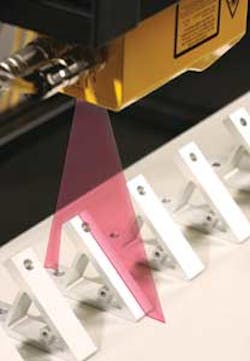
In applications such as pharmaceuticalblister pack inspection where a higher level of accuracy may be required, structured-light-based systems can be used to generate 3-D models. In such systems, a laser light line is projected onto a part and is captured by a camera either as the part moves along a conveyor or the laser/camera combination moves across the part. Multiple line profiles captured by the camera are then used to reconstruct the surface of the 3-D object.
Again, a number of off-the-shelf software packages are available that can be used as general-purpose tools or with specific 3-D hardware to reconstruct 3-D images from point cloud data. One of the most popular of these software packages is the SAL3D (3-D Shape Analysis Library) fromAqsense. A set of tools for processing point cloud information acquired from different 3-D vision technologies (including laser triangulation), the software is offered by Aqsense and can be combined with other software packages such as Matrox’s MIL, MVTec Software’s Halcon, and Common Vision Blox from Stemmer Imaging.
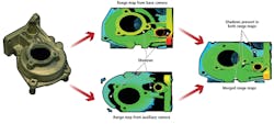
To minimize occlusions or shadows present when using single-camera laser triangulation methods, Aqsense’s SAL3D Merger Tool allows range maps from different cameras imaging the same scene to be merged to improve the quality of acquired data (see Fig. 1). As with many other 3-D methods, this requires prior calibration of the system with a known measured object. To date, Aqsense’s Peak Detector tool used for laser stripe detection has been incorporated into a number of FPGA-based cameras, most notably those from Photonfocus. The SAL3D package also has been embedded in systems such as those for dental imaging, automotive inspection, and food analysis.
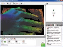
For system developers wishing to acquire structured-light-based 3-D images and 2-D images simultaneously, for example,Sick has teamed with Cyth Systems to develop 3-D vision software based around Vision Builder for Automated Inspection from National Instruments (NI). The configurable machine-vision software allows images to be acquired from the Sick Ranger camera and rendered in 3-D (see frontis and Fig. 2).
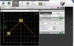
To ease the task of integrating laser and camera combinations, Sick andLMI Technologies offer products that combine both cameras and lasers into single products. Sick’s Ruler Series can be used to image a number of different fields of views of 3-D objects. Like Sick’s, LMI’s latest Gocator 2000 family is also offered in different versions, allowing the devices to be used at variable standoff distances and resolutions. LMI offers a web-based browser tool to control single or multiple devices, set triggers and exposure rates, and make measurements on captured 3-D image data (see Fig. 3).
Time of flight
Of course, the achievable resolution obtained by both stereo and structured-light-based systems will be dependent on the distance of the object from the imaging system. In applications such as pallet measurement, where required accuracy measurements may not be as stringent, it may be more effective to use time-of-flight (TOF) sensors.
In such systems, distance data are created in a manner similar to that of lidar scanners but the entire scene is illuminated with a laser or LED light rather than employing a moving laser. This type of sensor is available from a number of vendors, includingifm efector (IFM) and Mesa Imaging.
Targeted at materials handling applications, IFM’s TOF 3D Image Sensor employs a photonic mixer device fromPMD Technologies. In operation, pulsed LED light reflected from an object is detected by the image sensors, then comparing the optical and electrical reference signals yields an output that determines distance information. Point cloud information is used to generate a 3-D view of the object.
The SwissRanger SR4000 from Mesa Imaging employs TOF principles to generate point cloud data. To evaluate generated data, the company’s MESA Visualization Software GUI allows basic camera operations and views of point cloud data to be displayed and for object size and distance to be measured.
For more complex image measurements, MVTec Software and Mesa Imaging provide an interface to allow data generated by the camera to be used with MVTec’s Halcon software. This allows 3-D data representing distance and amplitude to be acquired within Halcon and morphology operations, 3-D matching, and 3-D measuring to be performed.
Company Info
Cyth Systems
San Diego, CA, USA
ifm efector (IFM)
Exton, PA, USA
LMI Technologies
Vancouver, BC, Canada
Matrox Imaging
Dorval, QC, Canada
Mesa Imaging
Zurich, Switzerland
MVTec Software
Munich, Germany
National Instruments
Austin, TX, USA
Photonfocus
Lachen, Switzerland
PMD Technologies
Siegen, Germany
Recognition Robotics
Elyria, OH, USA
Stemmer Imaging
Puchheim, Germany
Tordivel
Oslo, Norway
More Vision Systems Issue Articles
Vision Systems Articles Archives


