IMAGE PROCESSING: Vision system inspects medical fibers at high speed
Monofilament sutures (medical fibers) are manufactured using an extrusion process that requires tight quality control. To inspect these fibers, manual operators must accurately detect, localize, and catalog relevant manufacturing defects such as out-of-tolerance diameters, surface abrasions, internal flaws, gouges, and geometric abnormalities—a process that is both time consuming and subject to operator error.
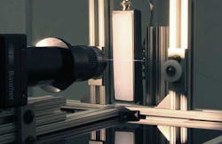
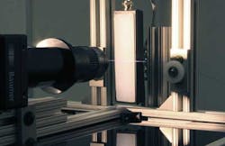
Adsys Controls (Irvine, CA, USA) has developed an automated system capable of inspecting abnormalities on medical fibers as small as 1 µm at rates up to 30 m/s. During manufacturing, the fibers are pulled at high speed through drawing systems where they are ultimately put into spools, before they can be sectioned and shipped as final product. Prior to spooling, the inspection system monitors the fiber for defects while classifying and recording the defect location and type. A diffuse white LED from Advanced illumination (Rochester, VT, USA) is used to backlight the fiber as it travels through the drawing stage.
A high-resolution zoom lens from Edmund Optics (Barrington, NJ, USA) is fitted to a 2048 × 1088-pixel HXC-20 Camera Link progressive-scan CMOS camera from Baumer (Radeberg, Germany) to begin imaging the fiber. Windowed images from the camera are transferred at 640 frames/s over the camera's interface to a ProLight Camera Link interface board from Adsys Controls.
To perform image processing at high speed, this board is interfaced to a 7954R FPGA-based FlexRIO module from National Instruments (Austin, TX, USA) that is mounted in a PXI chassis (see Fig. 1). A rotary encoder is interfaced to the Adsys ProLight through the board's general purpose I/O interface; it tracks the position of the fiber as it moves through the system. This enables the position of the fiber and the images to be correlated and displayed on the operator interface.
For image analysis, Adsys Controls employed its own library of FPGA algorithms for image-processing applications. Compatible with the Xilinx Virtex-5 LX110 FPGA, the software was used in conjunction with the LabVIEW FPGA module to perform functions including pixel decoding, tolerance measurement, and defect detection.
As images are captured, the software first locates the fiber in the field of view, compensating for fiber bounce through the imaging system. To compute the width of the fiber as it moves through the system, an edge-detection algorithm is applied to the image. Because light diffused from an abrasive surface will appear dark, defects in the fiber can be highlighted using image segmentation.
"Pipelining of image-processing algorithms take advantage of the parallel-processing capabilities of the FPGA to increase efficiency and reduce timing constraints," explains Brian Goldberg, president of Adsys Controls. "However, each algorithm structure—or re-entrant sub-virtual instrument (subVI)—running in parallel occupies its own real estate on the FPGA. Because of the limited logic on the FPGA, running very many parallel re-entrant subVIs could not be accomplished since there was not enough logic to properly accomplish all the tasks required."
To overcome this limitation, Goldberg identified areas in the image-processing algorithms where re-entrant subVIs could be changed to non-re-entrant subVIs. These algorithms were then implemented using loops instead of occurring in parallel. Non-re-entrant subVIs then save FPGA space since there is only one instance of the subVI on the FPGA (see Fig. 2). Although the timing of the algorithm remained the same, FPGA real estate was reduced by a factor of four.
After images are processed, they are displayed in real time in a user interface developed in LabVIEW. The operator can visualize the diameter of the fiber as it passes through the system as well as any defects that may be present. These defects and the position of the fiber can then be stored in a database for later retrieval.
To indicate the position of these defects on the fiber as it is wound, Adsys Controls plans to add a high-speed marking element to the system. In this way, any defects can be easily removed manually during the sectioning of the fiber. A complication to the marking system is the requirement that marking cannot contaminate the remainder of the fiber spool.

