Standard Gives Machine Vision Systems a New Image

The GigE Vision protocol is growing up

Since its launch in May 2006, the Automated Imaging Association's (AIA)GigE Vision standard has provided developers of vision systems with a reliable means to control cameras and transmit image data over a network.
The standard was initiated by a group of 10 companies and the committee behind it has since grown to include more than 50 members. The US-based AIA oversees the ongoing development and administration of the standard and its trademark is registered by the same organization.
Using devices that are compliant with the GigE Vision standard, developers can build systems that not only transfer video from a single camera to a single PC in a point-to-point (or unicast) mode but also share information and video across multiple clients, in a point-to-multipoint (or multicast) mode.
Because it is based on the IEEE 802.3 Gigabit Ethernet (GigE) data transmission standard, the GigE Vision protocol allows system integrators to add and remove nodes very easily in a network and to tailor their systems to custom requirements.
While Ethernet and Fast Ethernet are limited to 10 Mbits/s and 100 Mbits/s, respectively, the GigE Vision standard is speed-agnostic and allows images to be transmitted at 1 Gbit/s or higher data rates (such as 10 Gbits/s) over a variety of different types of cables.
A key benefit of the standard is that data can be transmitted over long distances. By using Cat 5e/6 cables explicitly rated for Gigabit Ethernet use, for example, engineers can build systems that can transmit image data over 100 m without regenerating the data, a range that can be extended further using switches or fiber cabling.
The specification divided into four
There arefour key elements that define the GigE Vision standard, and between them they explicitly specify how video is transmitted over the network and how devices on the network, such as cameras, are controlled (see Fig. 1).

The first of these—the Device Discovery protocol—defines how GigE-compliant devices obtain IP addresses and can be identified on the network.
When a GigE device is first powered up, it attempts to acquire an IP address in one of three ways. If it has already been assigned a permanent IP address, it will automatically attempt to use that address. If not, then it will attempt to acquire an IP address from a DHCP server provided that this option is enabled on the device. If neither of these proves effective, then the device will assign itself an IP address and search the network to determine its uniqueness, a process which it will repeat until it finds a unique address of its own.
The second element in the GigE Vision specification—the GigE Vision Control Protocol (GVCP)—defines how to specify stream channels, and to control and configure compliant devices (see Fig. 2).
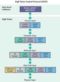
The GVCP itself has been built on top of the User Datagram Protocol (UDP). With UDP, computer applications can send messages called datagrams across an IP network without requiring prior communications to set up special transmission channels or data paths. Moreover, UDP is a simpler and leaner protocol than TCP.
But the developers of the GigE Vision standard recognized that the UDP protocol had one important drawback that needed to be addressed before it could be used as the basis of a standard for vision applications: It did not offer a means to guarantee delivery of data.
To rectify this matter, GVCP, a simple "command and acknowledge" based protocol, was defined as a layer over the UDP protocol. By doing so, an application can send a command to a device on the network and then wait for the device to send an acknowledgment back before the next command is sent. The protocol allows various attributes to be set up on a GigE-compliant device, such as the gain of a camera.
The third element in the standard—the GigE Vision Streaming Protocol (GVSP)—defines how a compliant transmitter will packetize and transmit data on the network (see Fig. 3).

Data are encapsulated in a block, which comprises a data leader that defines the specifics of the data—such as the width and height of an image—a data trailer, and a number of data payload packets. The GVSP supports different types of payloads, so it is not only possible to transmit video over the network but files and metadata as well.
Once again, however, because GVSP is also implemented on top of UDP, there is no handshaking method present to guarantee the delivery of packets of data, so the GigE Vision developers needed to create a means to do so.
This was achieved by defining a sequence of ID numbers inside the header of the GigE Vision packets. A transmitter sends the video packets, and a receiver then examines the sequence ID numbers to determine if image packets have arrived out of sequence and whether a packet is missing. If that is the case, then the receiver can request that the packet be re-sent.
The last part of the GigE Vision standard—the GenICam XML Device Description file—defines the features supported by the device. To comply with GigE Vision, seven mandatory features must be present in the XML file.
The description takes the form of an XML device description file following the format defined by the GenApi module of the GenICam standard, a computer-readable datasheet that is generally embedded inside the camera. The beauty of the GenICam XML concept is that it enables a generic software application to download the XML file from the device over Ethernet to determine its capabilities.
A revision of GigE Vision
Since its introduction, the GigE Vision standard has undergone two revisions. While Version 1.0 defined the protocols for video streaming and device control over Ethernet networks, it focused on defining the means by which PCs and cameras could communicate over traditional point-to-point connections.
In April 2009, the standard went through a minor update, resulting in the release ofVersion 1.1. Version 1.1 included new pixel formats and Bayer packed formats support, a means to automatically detect the speed of the link between devices, and enhanced support for Version 2.0 of the GenICam standard, allowing cameras to support multiple versions of the GenICam XML Device Description schema.
In addition, support was also added to allow commands to be sent to multiple devices simultaneously. To facilitate the deployment of GigE Vision systems in more applications, improvements were also made that enabled it to be used in systems that employ firewall protection mechanisms.
In January 2010, the standard went through another minor revision—toVersion 1.2—which enabled several new classes of GigE Vision products to communicate across the network. These include not only cameras that generate GigE Vision-compliant video streams, but PCs running video processing and display applications, as well as a variety of other hardware and software products that together comprise a complete video distribution system. This extensive list of products includes video servers that can feed video data onto the network, software- or hardware-based video processing units, and HDMI/DVI-compliant devices that can display video feeds from the network directly onto a monitor (see Fig. 4).
Depending on the type of GigE Vision-compliant product to be created, up to four building blocks can be used: an application that functions as the master of the GVCP control channel; a device that is itself controlled by GVCP; a GVSP-compliant video transmitter; and/or a GVSP-compliant video receiver.
Using these building blocks, a full spectrum of GigE Vision-compliant products can be created. For example, a camera would employ the following building blocks: a device controlled by GVCP and a GVSP-compliant video transmitter. A software-based video processing unit, on the other hand, would employ these building blocks: a device controlled by GVCP, a GVSP-compliant video transmitter, and a GVSP-compliant video receiver. A receiver and control software, however, would typically employ an application and a GVSP-compliant video receiver.
Version 1.2 of the standard also provisioned for those nonstreaming devices that do not receive or transmit any video, such as strobe light controllers that can be controlled over the network. Additionally, the GigE Vision standard text also defined how to make video network management entities compliant. While these software applications do not themselves send or receive video, they control the various elements of the video system that do.
Editor's note:In Part II, Vincent Rowley will describe the features and capabilities of the new GigE Vision 2.0 standard, which was released at the end of last year.