Smart Cameras Think Outside the Box

Smart cameras with embedded processing capabilities are changing the vision landscape, allowing developers to run vision inspection applications without the need to burden a separate PC
Dave Wilson, Senior Editor
Although many descriptions of smart cameras are offered by manufacturers, no one unifying definition exists. Generally speaking, however, a smart camera is one with some processing capability built in. This can take the form of a dedicated field-programmable gate array (FPGA), a digital signal processor (DSP), a fully fledged CPU or CPU/GPU combination from a processor vendor such as Intel or AMD, or a CPU supported by an FPGA.
Because of their inherent programmability, smart cameras are now finding their way into a number of niche applications once dominated by camera/PC software-based combinations. However, the choice of smart camera and development environment is dependent on the nature of the vision inspection application, the cost and volume of the system in which the camera will be deployed, and the ease with which it is to be programmed.
Drag and drop
Today, manufacturers of smart cameras are leveraging the ease of use of their associated image-processing tools, so an end user with relatively little vision experience could potentially develop image-processing systems. Because the camera hardware and software represent "out of the box" solutions, applications require fewer programming skills and therefore are appealing to those developers of vision systems eager to reduce costs.
Certain vendors of FPGA-based cameras, for example, offer libraries of functions that make it possible for system integrators to perform some form of preprocessing on an image before it is transmitted over a network. This type of customized functionality includes sensor-specific functions such as image correction, Bayer correction, and more application-related functions such as 3-D laser triangulation and color classification.
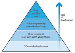
Smart cameras based on commercially available microprocessors or DSPs with or without FPGAs, on the other hand, can be programmed in a number of different ways and with applications developed to run under operating systems such as Windows, Solaris, Linux, or multitasking real-time operating systems (see Fig. 1).
To enable devices to be programmed quickly, many camera vendors provide graphical integrated development environments (IDEs) that enable system integrators to customize a vision algorithm by choosing specific "canned" functions from a library and interconnecting them.
Many toolkits are also available with which a user can create a custom GUI in a similar fashion by dragging and dropping controls from a library onto a human-machine interface (HMI) panel, setting the control properties and connecting the controls to the vision functions. PPT's Vision Program Manager (VPM), for example, is a software environment that helps developers create a range of vision and optical character recognition (OCR) programs, while its Control Program Manager (CPM) can be used to build custom control panels (see Fig. 2).
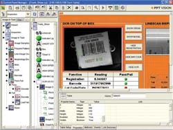
Some cameras that use drag-and-drop libraries to allow user programming of the camera's vision functionality can also be programmed in more conventional industrial programmable logic controller (PLC)-style languages. For example, Festo's smart camera can run a number of off-the-shelf vision applications such as barcode reading and OCR. It also has the ability to be programmed similarly to a PLC (see Fig. 3).
Software development kits (SDKs) may be well suited for one-off projects that need to be implemented in a short period of time—perhaps a few days or weeks. Although the cost of the camera and the SDK required to develop the application may be higher than the cost of developing software from scratch, costs will be amortized by the reduced amount of time required to develop the application.
As effective as such approaches are, developers of smart camera systems may also require the ability to perform some form of script programming to customize certain parameters. Certain text-based scripting tools come with a script interpreter to render compiling of the completed code unnecessary. Many are also offered with integrated web servers that make the intelligent cameras web-compatible, allowing system developers to control the camera via a remote server.
The more complex and lengthier task of creating image-processing code in a high-level language such as C or C++ for a smart camera may be a better solution for engineers developing systems in greater numbers. Although the initial cost of developing code for the application may be higher than using off-the-shelf graphical software, the costs will be amortized due to the number of systems to be built.
The advantage of such an approach is that by developing, or using, libraries of processing routines that perform specific functions such as blob or edge detection, developers no longer need to pay for image-processing functions in libraries that may not be needed, cutting the per-unit costs of the implementation.
Having said that, vendors advocating the C++ programming approach are also aware of the need to assist less experienced programmers to get to market quickly. For that reason, they may allow developers to use environments such as Microsoft's Visual Studio, an approach that allows software to be tested and debugged directly on a PC.
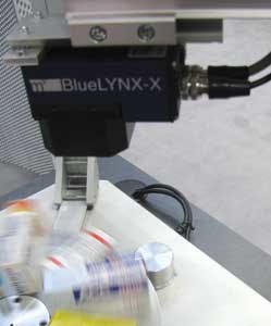
Although some software programming environments are specific to an individual camera manufacturer, there are also many packages that are agnostic and can be used with cameras from numerous vendors. While these packages might have once appeared to be an expensive option for developers, today software developers are increasingly unbundling the software, allowing system integrators to choose and pay for only the specific image-processing functionality that they require. Matrix Vision's BlueLYNX camera, for example, can be programmed using MVTec's Halcon software (see Fig. 4).
This unbundling approach may ultimately result in drag-and-drop algorithms being offered to system integrators in much the same way that Apple now offers apps for the iPhone and iPad. With such a universal library of functions open to them, developers would then be able to choose the specific image algorithms that best meet their price and performance requirements from whatever vendor they prefer.
While the performance of many of the processors currently found in smart cameras might be sufficient to handle simple optical recognition tasks, if a developer needs to perform more complex image-analysis functions such as rotational matching or surface feature matching—or process high-resolution images—then more processing power may be required.
Fortunately, many software vendors offer timing tools that can gauge the execution times of a program prior to deployment on a smart camera, so developers can judge how computationally intensive their programs are.
Of course, the dynamic nature of the industry means that the power of the processors found in smart cameras continues to increase. This year saw the introduction of a smart camera that combines a main processor and a graphics processor on the same device. Undoubtedly, this trend will mean that an increasing number of more complex imaging algorithms will fall into the remit of the smart camera.
System interfaces
While smart cameras can perform many image-processing tasks, system integrators still need to interface the camera to other components in a system. Because of this, many smart cameras support Ethernet, RS-232, or 24-V output channels over which developers can send simple pass/fail information. Many also support either a VGA or SVGA output mode, allowing captured images or an HMI to be visualized on a monitor.
If data need to be acquired from a camera for later analysis, then the ability to interface to some storage device such as a hard drive on a PC may also prove advantageous. In this way, the PC can record statistical data from the image analysis so that a quality control department can analyze the data at a later point.
In systems where multiple cameras may need to be deployed, however, smart cameras may prove incapable of meeting the demands of the application. Even if they are, they may be a more expensive option, as developers will be required to pay for multiple application software licenses from the camera manufacturer or incur greater costs for the camera hardware.
In these instances, multiple "dumb" cameras, a single multicore PC, and a single application software license may still prove a more viable and cost-effective approach, since the power of the PC will inevitably outpace the somewhat lower performance of the embedded processors in the cameras themselves.
Having said that, even some developers of high-end image-processing systems have deployed smart cameras when the processing and bandwidth demands of their multicamera systems required them to offload certain processing tasks onto the smart cameras!
Expert advice
As attractive as a smart camera might be, system integrators may still be called upon by sophisticated end users to help facilitate the development of a smart camera-based system, a process that may involve the duplication of the inspection setup at the customer's premises to ensure that the single-camera inspection system will work as specified.
An integrator may need to ensure that the lighting and the optics used in the system are appropriate to make the processing task straightforward enough for a smart camera to handle. After a subsequent demonstration, the system integrator may then be asked to undertake an on-site trial, commissioning, and training.
Although the work is time consuming—it may take a system integrator several days to perform the exercise—and does add to the price, the overall result should be a system that would be less expensive and faster to commission than a vision-based PC solution.
Automated wheel assembly uses smart cameras
Using manual assembly methods to mount wheels onto cars in continuous operation is extremely costly for automotive manufacturers, mainly because several assembly workers are required to perform the task.
Now, IBG Automation GmbH has designed an assembly system for the automotive industry that automatically fits and mounts wheels onto car bodies moving continuously along the line. By automating this process, automotive manufacturers not only see labor costs drastically reduced but overall manufacturing quality improve as assembly errors are eliminated.
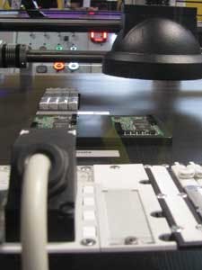
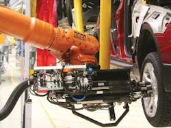
Two 6-axis Kuka industrial robots—one located on each side of a car body—gather wheel bolts and rims from their supply stations and screw them onto the car. The robots are synchronized with the conveyor and follow the car's movement during assembly. Attached to each robot is specialized lighting with polarized and infrared filters (see Fig. 1).
A Matrox Iris GT smart camera is also attached to each robot. The smart camera locates the rim's center point and calculates its position (x, y), rotation (Rz) of the bolt circle, and distance to the camera (z) in calibrated coordinates (see Fig. 2). Before these coordinates are given to the robot, the smart camera checks to see whether the rim design that it has located matches the rim that is expected to be given by the PLC.
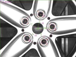
This last test prevents the wrong rim design from being mounted on the vehicle. Thirteen different wheel combinations—seven rim designs and four types of lacquer (white, silver, anthracite, and black)—are identified. The entire automated wheel assembly process has a cycle time of only 54 s.
The image-processing system is based upon the Matrox Iris GT smart camera, and the application developed with Matrox Design Assistant, an IDE that is bundled with the camera.
The IDE lets users create machine-vision applications by constructing a flowchart instead of coding programs or scripts using languages such as C++. Once development is finished, the project (or flowchart) is uploaded and stored locally on the Matrox Iris GT. The project is then executed on the smart camera and monitored from the web-based HMI running on a PC.
A number of Design Assistant tools or flowchart steps were used. Image acquisition and processing are triggered by a command from a network, which contains information about the measurement job and the expected rim type. Several Model Finder steps are used to locate the wheel's bolt circle and to verify the expected type of design. A Metrology step then calculates the rim's position and orientation based on data provided by the Model Finder occurrences.
A TCP/IP connection ensures communication between the smart cameras and the PLC. Results and images are logged to a shared network folder—using TextWriter and ImageWriter steps—and can be downloaded by remote maintenance staff for fault analysis.
The system needed to be able to handle different design and color combinations along with overlapping rims. An algorithm based on Matrox's Geometric Model Finder and Metrology steps was required to only use the indicative features belonging to the rim in the foreground while discarding those that belong to rims behind it.
Other challenges included having different settings for image acquisition and Model Finder steps on each side of the assembly line and for each rim type, in addition to ensuring reliable depth measurement with a 2-D camera.
In summer 2009, the assembly system was deployed at Magna Steyr to mount wheels on BMW X3s. The assembly line was then modified in summer of 2010 to accommodate the different rim designs for the new Mini Countryman.
Company Info
Festo
Hauppauge, NY, USA
www.festo.com
IBG Automation GmbH
Neuenrade, Germany
www.goeke-group.com
Magna Steyr
Graz, Austria
www.magnasteyr.com
Matrix Vision
Oppenweiler, Germany
www.matrix-vision.com
Matrox Imaging
Dorval, QC, Canada
www.matrox.com/imaging
MVTec Software
Munich, Germany
www.mvtec.com
PPT Vision
Minneapolis, MN, USA
www.pptvision.com