Structured Light System Inspects Ski Surfaces

Thor Vollset
Cross-country skis are manufactured around a foam core that is sandwiched by two composite layers on the top and bottom, and sidewalls on the sides. While the top layer is patterned with the manufacturer's logo, the base of the ski must be perfectly formed to ensure maximum performance. Ski manufacturers such as Madshus use a process known as base grinding to remove any base imperfections. After the base of the ski is ground, it will still need to be inspected to detect any remaining imperfections.
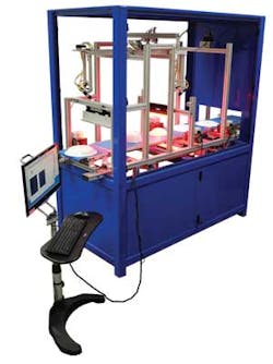
Madshus enlisted Tordivel to develop a laser-based profiling system that computes the surface detail of the base of each ski as they move along a conveyor at 250 mm/s (see Fig. 1). Due to the nature of the base grinding process, any defects will appear in a longitudinal direction along the ski. To detect defects as small as 0.02 mm in depth and 2 mm in length, the Tordivel system illuminates each ski as it passes along a conveyor with a structured laser light unit from Coherent.
Embedded in Tordivel's Scorpion 3D Stinger camera system, this structured light source illuminates the transverse section of the ski with three structured laser lines. Reflected light from these lasers is then imaged using a 640 × 480-pixel V60 GigE camera from Sony that is also embedded in the Scorpion 3D Stinger. Placed 250 mm under the conveyor, the 3-D camera system captures images at 90 frames/s and transfers them over the GigE camera's interface for real-time processing.
Automated and accurate 3-D calibration
Before any processing can occur, the system must be calibrated. Tordivel has developed its own calibration procedure based on a custom 3-D sawtooth test target. The aluminum target was fabricated on a CNC machine and painted black to achieve uniform reflection from the structured laser light sources.
As these sources illuminate the test target, the known placement of the target and its dimensions allowed each laser to be calibrated to a 5-μm accuracy. This is achieved by illuminating the test target with the three-line laser, then transferring the captured image to the host PC. The Scorpion 3D Stinger software automatically extracts the projections of the three laser lines and stores the 3-D calibration, which is used to convert the laser profiles to height with sub-pixel resolution.
Multiple lasers
Other 3-D structured-light-based systems use a single laser to illuminate objects as they pass along a conveyor, but this approach could not be taken in the ski measurement system. Since each ski is curved and may move as it traverses the conveyor, an imaging system based on a single laser light solution would only effectively measure the relative position of the ski across its transverse section.
Because such motion is unpredictable, an accurate measurement of the profile could not be achieved in this manner. However, using three line profile measurements across the ski and taking a differential measurement between these lines could compensate for any motion error, resulting in an accurate profile deviation measurement needed for grinding defect detection.
The system needed to accommodate a number of different types of skis, all with different lengths and widths. To allow for these variations, the system was also required to compute the edges of each ski as it passes along the conveyor so that accurate laser measurements of the surface could be computed.
Image analysis
After image data are transferred to the host PC, the line profiles of each of the three laser lines are analyzed and edge detectors are used to first highlight the edges of each ski (see Fig. 2). The result is then displayed as a series of green dots on the system's monitor. Once these edges have been computed, the information can be used to calculate the centerline of each ski.
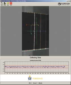
The ski is not uniformly flat in the center, so computation of this centerline is important; calculation of the values of the transverse results from each laser only need to be performed when they fall outside of the centerline. This result is displayed as a series of red dots on the system's monitor.
Once the height differences of these points are calculated, the results of the height differences are averaged for each laser line. The height differences between them are then calculated and displayed on the system. Although the height differences are calculated transversely, the differences between them will give a value of the line profile in the longitudinal direction of the ski—i.e., along its length.
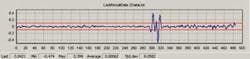
Since each ski is approximately 2 m long and passes along the conveyor at 250 mm/s, it takes approximately 6 s to pass over the vision system. During this time, the system images 80 three-line profiles of the transverse section of the ski, resulting in a system capable of detecting defects as small as 2 mm in the longitudinal direction and 0.02 mm in depth. The depth resolution is 1/10 of a pixel = 0.2 mm (see Fig. 3). Thus, by plotting the maximum deviation between the three laser-line values, the operator is presented with a curve that visually demonstrates the defects along the ski. To determine whether a ski should pass or fail the inspection, the operator can set a predetermined threshold value in the system's graphical user interface (GUI). This is shown in red in Fig. 3.
Pass or fail
Should a ski pass inspection, it continues along they conveyor to be packaged and shipped. Should the ski fail such an inspection, the industrial PC with an Intel quad-core CPU running the system triggers a programmable logic controller (PLC) to stop the conveyor. An operator then removes the ski, which is either rejected or sent for further grinding.
Tordivel employed the new Scorpion Vision Apps available via its Scorpion Vision Software to configure a custom and minimal GUI. The interface allows the operator to perform simple system functions such as starting and stopping the system, resetting the threshold value, and analyzing statistical data. To perform more advanced system reconfiguration, a password-protected settings mode can be accessed.
Presently, the $20,000 system has been in use at Madshus's facility for more than 10 months. In the future, Tordivel expects to introduce further enhancements to such 3-D systems including standalone systems that employ a multitude of laser lines to do 360° measurement of pipes and rods and stereo-vision-based laser triangulation with higher accuracy than conventional 3-D laser triangulation systems.
Thor Vollset is CEO and founder of Tordivel AS (Oslo, Norway).
Company Info
Coherent Inc.
Santa Clara, CA, USA
Madshus
Biri, Norway
Sony Electronics
Park Ridge, NJ, USA
Vision Systems Articles Archives