Leverage Lenses for Better Vision
Andrew Wilson, Editor
As with many tasks involved with choosing OEM components for machine-vision systems, deciding on which lens to specify for a given application can be challenging. Although the optical fundamentals of how lenses may perform are well documented, manufacturers are often unwilling to divulge even the basic characteristics of their products.
Faced with a lack of this important information, many system integrators are tasked with testing numerous lenses before deciding which is best for their application. Luckily, third-party distributors such as1st Vision are now taking up this challenge, evaluating multiple machine-vision lens options. Of course, as Scott Israel, president of 1st Vision, points out in his presentation "Untangling the megapixel lens myth" (see http://bit.ly/KQTvd6), even with the right data, choosing a lens is made more difficult by the unique demands that each machine-vision system will place upon it.
However, there are a number of online tools that allow system developers to narrow the search for potential lenses that may be useful in any given application. One freely available tool is the MachVis lens selector program fromQioptiq that can be downloaded from http://bit.ly/KZX7pr. Written by Geoff Adams, PhD, the software package allows users to vary the size of the object to be imaged, its distance and size, the size of the image sensor, its pixel size, and the lens mount required (see Fig. 1).
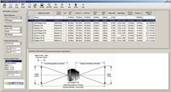
Thus, once the size of the sensor used in the camera is known as well as its field of view (FOV), and the distance from which the object is located in front of the lens, the calculator will determine the focal length of the lens required. The software automatically computes which of the company's lenses meets the specific criteria, returning detailed data such as the effective focal length of each lens.
While this type of calculator will return the exact focal length of a lens required, lenses with that focal length may not be available. For example, the calculations may reveal that a 38-mm lens is required. To achieve this focal length, an extension tube or extension ring can be added to a 35-mm lens to increase the lens-to-sensor image plane distance (the focal length). But since the lens will be farther from the image plane than it was originally, this change will result in a smaller FOV, an increased magnification, and a loss of light transmitted through the imaging system.
Spatial frequency
Unfortunately, unlike FOV, the quality of a lens cannot be measured as a single number or described in a single statement. Factors such as contrast and distortion must be taken into account. To understand how a particular lens will resolve objects, it is useful to measure its spatial frequency response or modulation transfer function (MTF). Essentially, the MTF is a measure of how well a lens will resolve a series of line pairs spaced at increasingly closer periods. At low frequencies, lenses will exhibit an MTF of nearly 100% but the frequency response will diminish at higher frequencies.
In developing MTF charts, the working distance of the lens, its aperture, and the spectrum in which it operates should also be provided because these factors will affect the MTF (see "Specifying lenses for megapixel cameras," Vision Systems Design, November 2009). Needless to say, for any given lens, numerous MTF charts could be developed, a challenge undertaken by relatively few manufacturers.
Distorted images
Similarly, there are many different types of distortion associated with lenses. These include radial distortion such as barrel and pincushion distortion, as well as lateral and longitudinal chromatic aberration. Depending on the application, radial distortion may have little or no effect on providing the accuracy required. Where distortion may compromise system accuracy, it can be compensated for using camera calibration software from a camera vendor or third-party vendor.
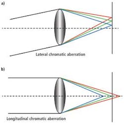
When obliquely incident light falls on a lens, any lateral chromatic aberration will mean that, while the different frequencies of light may all be in focus, they will be in focus along different points in the optical axis. This leads to fringing effects in the color image. Axial chromatic aberration results in different frequencies of light that may fall in front and behind the focus position (see Fig. 2).
Like radial distortion effects, chromatic aberrations may be compensated for using software. Alternatively, by using achromatic and apochromatic lenses, two or three different frequencies of light can be focused at the same point on the image plane to optically compensate for axial chromatic distortion. Such lenses are especially useful in applications that require color to be accurately rendered.
Optical options abound
Understanding lens quality is important, but so too is a familiarity with the type of lenses that can be deployed. In many machine-vision systems, fixed-focal-length lenses are used. Most of these lenses feature locking screws to set the iris and focus adjustments to ensure system stability even in the presence of vibration. They support most commonly used 1/3-, 1/2-, 2/3-, and 1-in. imager formats as well as large linescan 90-mm imager formats.
When using fixed-focal-length lenses for high-performance gauging applications, it is often necessary to ensure that the sensor's orientation is properly aligned with the optical axis of the lens. For this reason, in its line of Macro-Symmar lenses designed for 12k × 1-pixel linescan applications,Schneider Optics provides a V-mount interface that allows proper alignment of the lens for the best average azimuth position with respect to the linear array.
Conventional fixed-focal-length lenses may be the most popular choices for machine-vision applications, but of course other, more application-specific lenses are also available. In high-precision gauging applications, telecentric lenses can eliminate the perspective effects commonly found with conventional lenses. They are generally offered as object-space telecentric, image-space telecentric, or bilateral telecentric designs. In object-space telecentric lenses, the chief rays of the lens are parallel to the optical axis and the lens focuses these rays onto the camera's image sensor.
Unlike conventional lenses where objects of the same size placed at different distances from the lens will appear to be different sizes, objects of the same size placed at differing distances from a telecentric lens will appear to have the same size. In precision gauging applications, this is especially useful. To increase this accuracy further, double-sided or bi-telecentric lenses can be used in which telecentricity exists in both the object and image plane. This further reduces any optical distortion and allows objects to move through a larger range within the lenses' depth of field while retaining the same magnification.
In many machine-vision systems, telecentric lenses are used to image the object being measured as well as provide collimated lighting -- which allows the edges of objects to appear sharper and thus increases measurement accuracy.
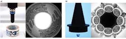
More novel approaches are being used to measure multiple views of objects using single lenses. In the design of its so-called pericentric lenses,Opto Engineering has produced a lens that allows one camera to capture the image of both the front surface of an object and its surrounding sides.
When viewing a cylindrical object, this feature allows both the front surface and the cylinder surface to be imaged simultaneously. Although useful, specialized imaging software is required to reconstruct the captured image (see "Lens Designs Tackle Novel Vision Applications," Vision Systems Design, July 2011). Other specialized lenses from Opto Engineering such as the company's range of Hole Inspection Optics and Polyview Optics allow the insides of objects and multiple views of the side and surfaces of an object to be imaged, respectively (see Fig. 3).
Learning more about lenses
In choosing a lens for a machine-vision application, many factors must be taken into account. Luckily, a number of white papers, tutorials, and videos are now available for those about to embark upon such a task. Realizing that video tutorials are the best way to present this information, bothEdmund Optics and Opto Engineering have developed their own YouTube channels, which can be viewed at http://bit.ly/Ms99xn and http://bit.ly/L7gzk0, respectively. Tutorials on many aspects of lens parameters are also available on the web (see "Machine-vision lens tutorials" below). Despite this, many vendors are still reluctant to offer detailed descriptions, tutorials, or videos describing the performance of their products, leaving the task of lens evaluation to system developers.
Machine-vision lens tutorials
How to read MTF Curves
Depth of field calculator
Depth of field
Debunking the Megapixel Lens Myth!
Longitudinal and lateral chromatic aberration
Lens mounts for machine vision cameras
Fundamentals of selecting a lens
Optics resolution applied to machine vision
Machine-Vision Lens Vendors
CBC America
http://computarganz.com
CVI Melles-Griot
www.cvimellesgriot.com
Edmund Optics
www.edmundoptics.com
Goyo Optical
http://goyooptical.com
Kowa Optimed
www.kowa-usa.com
Navitar
http://navitar.com
Opto Engineering
www.opto-engineering.com
PENTAX Ricoh Imaging
http://bit.ly/MRHlkg
Qioptiq
www.qioptiq.com
Schneider Optics
www.schneideroptics.com
Sill Optics
www.silloptics.de
Tamron
www.tamron.com
Universe Kogaku America
www.ukaoptics.com
VST USA
http://bit.ly/KYIDKE
To find more lens vendors, please visit the lenses section of theVision Systems Design Buyer's Guide (http://bit.ly/L7hF0z).