Linescan Camera System Scores a Hole in One

A winning combination of image-processing software, linescan cameras, and a patented feeder/gripper system addresses the challenges of inspecting round objects at high speed
Andy Wilson, Editor
Manual inspection of products has its place in many facilities, but manufacturers seeking to reduce the occurrence of defects and improve the yield of higher-quality finished goods often find themselves in need of automated systems that can address the unique demands of their production processes. For example, taking all of the factors for inspecting a high-quality, printed object such as a golf ball -- with round and textured surfaces -- into consideration, an inspection system requiresnovel automated handling equipment that can feed these objects into the inspection stations at high speeds to keep manufacturing moving. It also must deliver a highly accurate inspection on multiple parameters through the use of integrated cameras, lighting, optics, and image-processing software that are carefully selected for maximum production throughput with minimal defective product being allowed to pass through. Read on to learn more about how to address the unique requirements of inspecting round objects at high speed.
Competitive challenge
With the price of top-quality golf balls now reaching as much as $4 each, manufacturers recognize that to remain competitive each ball must be of the highest standard. Since any printing or surface defects, dirt marks, ink smudges, or excess paint may be deemed unacceptable, each ball must be thoroughly inspected. Should defects be minor, the ball can be sold as a lower-quality item. If the defect is more severe, then it must be rejected.
"In the past," says Ralph Carlson, president of Strategic Automation, "manual inspectors were tasked with inspecting statistical samples of golf balls for defects." Determining a need for a fully automated system, Carlson and his colleagues have developed the Sentry-1, which is capable of inspecting golf balls at speeds of up to 30 balls/min (see Fig. 1).
Vision in motion
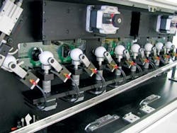
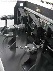
Strategic Automation has integrated a patented ball-manipulating system, custom lighting and optics, and off-the shelf cameras and software to perform the inspection (see Fig. 2).
During operation, golf balls are first fed from a hopper-based feed system into the entry chute of the system (Fig. 1, left). As can be seen, nine grippers are then used to move the ball through three imaging stages in the machine. A video of the machine in use can be seen athttp://bit.ly/Ng3kmf.
"Before any inspection can be accurately performed on each ball," says Carlson, "the orientation of the print on the pole positions and the side of each ball must be determined." Once this is accomplished, the ball can be later oriented so print marks at the pole and side positions can be more accurately imaged.
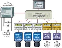
To determine the position of print on each ball, the first gripper picks a randomly oriented ball from the entry chute and places it in position in the first imaging stage. Here the ball is rotated about its axis and imaged by a 512 x 1-pixel, 65-kHz Camera Link linescan camera fromTeledyne DALSA fitted with a 35-mm Fujinon lens.
Images are transferred to an R3-CL Camera Link frame grabber fromBitFlow to the memory of a PCA-6186 industrial PC from Advantech. Using HALCON image-processing software from MVTec Software, the captured linescan image is unwrapped and thresholded, and blob analysis is applied to locate the position of the print on the ball. The ball is then indexed through the machine by the second gripper that reorients it by 90°. Using the same technique, any print on the opposite pole of the ball can be located and the relative positions of the print on each ball determined.
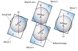
Rather than use a second camera to perform this image analysis, Carlson and his colleagues have used an optical stacked mirror system that usesEdmund Optics' R43-876 first-surface mirrors to allow a single 512 x 1-pixel linescan camera to image golf balls at these different orientations as they are stepped through the system (see Fig. 3).
Higher resolution
Once the relative position of the print is determined, the ball is indexed through a second imaging station to capture high-resolution images of the print located on the poles and equator of each ball (see Fig. 4). "It takes three rotations of each ball over three perpendicular axes to properly orient the ball," says Carlson, "a task that is performed by the third, fourth, and fifth of the grippers shown [in Fig. 1]." For more information on how this is accomplished, Carlson's patented method for performing this task can be found athttp://bit.ly/LeJWjZ.
This second imaging station comprises a 2k x 1-pixel, 18-kHz Teledyne DALSA Camera Link camera mounted with an 85-mm Nikon lens and is again used to digitize an image of the ball as it rotates around its axis. The images are transferred to the host computer using a second Camera Link frame grabber board, also from BitFlow. Once these images are digitized, they are again unwrapped and thresholded and MVTec's HALCON print-quality inspection software used to automatically grade the print quality (seehttp://bit.ly/Ny8DvV).
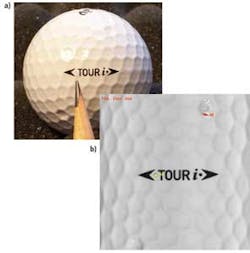
"This software uses a ‘variation model,' which is created by inputting numerous examples of good printing (in our case, 20 samples) to show the allowable variation in the printing," says Carlson. The ball being inspected is compared to this variation model, which greatly reduces false rejects caused by slight variations in the printing due to the dimpled surface. Because the camera and lens combination resolves 400 pixels/in. or 0.0025 in./pixel, defects as small as 0.003-in. diameter can be measured. Figure 5a shows a ball with a dot missing before the word TOUR. In the resulting inspection image (Fig. 5b), the missing ink has been detected and is shown to be 46 square pixels in area. The operator can set the allowable size of the defects.
In this second stage of the imaging system, a similar setup is used to image print on opposite poles of the ball. This is achieved by the fifth gripper that reorients the ball by 90°. Once again, the second stage-mirror-based imaging system allows golf balls to be imaged in two different orientations as they are indexed through the machine.
Dimple defects
After the print inspection is complete, each ball must be inspected for defects such as flashing, pits, paint, and dimple quality. Each ball is once again rotated through 90° to a third imaging station. Here, a second Teledyne DALSA 2k x 1-pixel, 18-kHz linescan camera coupled to a third BitFlow frame grabber transfers an image of the ball to the host computer as it is rotated around its axis.
"Because flashing, pits, paint, and dimple defects do not provide a good contrast against the background image of each ball," says Carlson, "it was necessary to develop a custom LED white light that provides off-axis illumination as the ball is rotated. Since such lighting will cause any defects to appear as shadows within the image, the defects can be more easily detected."
Captured images are thresholded and blob analysis is used to highlight any defects. Finally, the golf ball is rotated through 90° and the same analysis performed. "In this way," says Carlson, "any defects that occur across the complete surface of the ball can be classified."
After classification, inspected golf balls exit the machine where, depending on the quality, they can be transferred to separate bins to be correctly packaged. Strategic Automation has the Sentry-1 machine, or similar machines, installed at most of the world's largest golf ball manufacturers.
Company Info
Advantech
www.advantech.com
BitFlow
www.bitflow.com
Edmund Optics
www.edmundoptics.com
Fujifilm North America
www.fujifilmusa.com
MVTec Software
www.mvtec.com
Nikon
www.nikonusa.com
Strategic Automation
www.strategic-automation.com
Teledyne DALSA
www.teledynedalsa.com