HIGH-SPEED IMAGING: Time-of-flight camera captures VGA images at high speed

Numerous methods have been proposed to capture 3-D images, including those based on time-of-flight (ToF) technology. Such cameras resolve distance measurements by measuring the time of flight of modulated light (usually from LEDs) that is reflected from the object in the camera's field of view.
A number of companies including Mesa Imaging (www.mesa-imaging.ch) and PMD Technologies have developed ToF cameras that operate by modulating the light with an RF carrier and measuring the retuned phase shift of the carrier as the light is reflected from an object. An evaluation of both the Mesa Imaging Swiss Ranger SR4000 and PMD Technologies CamCube 3.0 has recently been performed by Dario Piatti and Fulvio Rinaudo of the Torino Polytechnic (www.polito.it). The results of their evaluation can be found at http://bit.ly/UQpTSF.
Direct ToF cameras have also been developed by other companies, most notably Advanced Scientific Concepts (www.advancedscientificconcepts.com) and SoftKinetic (www.softkinetic.com). Such systems are useful in certain stereo measurement applications because of the ability to easily compute the depth values for each pixel in the image and rapidly generate 3-D profiles.
"While useful, such systems are somewhat limited by the size of the imager, which is often less than VGA resolution," says James Munro, chief technical officer of Munro Design & Technologies.
To overcome this limitation, Munro has developed a patented prototype ToF system that uses an off-the-shelf, high-resolution, high-speed camera to allow VGA images to be captured at video rates.
The system employs a 3-in.2 bank of thirty 850-nm LEDs that are modulated by a 50-MHz waveform generated from a Xilinx Spartan 6 field-programmable gate array (FPGA). Reflected sinusoidally modulated light returning from the target is captured using a 50-mm lens from Nikon (www.nikonusa.com) with an aperture of f/2.0, and filtered by a narrowpass optical filter centered at 850 nm. A photocathode is then used to convert the incoming photons into an electrical signal that is amplified by a microchannel plate (MCP) image intensifier from Photonis (www.photonis.com).
Using the MCP, the intensity of the returning light is magnified by many orders of magnitude. By switching the MCP on and off in a few nanoseconds, the returning signal can be sampled both temporally and spatially. The resulting sampled and amplified signal is converted back to photons by way of a fluorescent screen within the MCP. Emitted photons from the screen are then imaged onto a Phantom v7.3 11,000 frames/sec, 512 × 512-pixel camera from Vision Research. Images from this high-speed camera are then downloaded to a PC over a Gigabit Ethernet interface.
To determine the distance and amplitude of each pixel in the image, a discrete Fourier transform (DFT) is executed on every pixel. Four samples of the received signal for each pixel must be made so that a four-point DFT can be performed (see Fig. 1). By switching the MCP on and off in 5-nsec durations in 90° increments along the 50-MHz emission waveform in equivalent time periods, four phase samples of the retuned light can be measured.
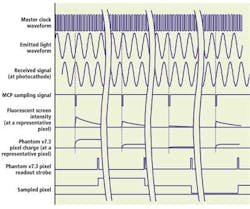
This process results in a different screen intensity on the fluorescent screen at each of these points since, for any given pixel, if the sample is made at the peak of the signal it will be brighter than if made at the trough. These four sampled points are then captured by the Phantom v7.3 camera for every pixel in the image, resulting in pixel magnitudes that are representative of the intensity of the phase value of the light at each position. Using these four values, the phase (Φm) of the received signal at any given pixel (m) can be computed as
From this phase, the corresponding distance (Dm) and amplitude (Am) from the object being imaged can be computed as
where ΔΦm is the difference between the phase of the received signal at a given pixel (m) and the phase of the signal at an arbitrary reference location such as the front of the 3-D imager. The amplitude of the mth pixel can be computed as
Even though the Phantom v7.3 has a bit depth of 14 bits, each individual frame from the v7.3 has a substantial amount of noise that degrades the distance-measuring performance of the system. To reduce this noise, several hundred frames of sampled image data can be collected and averaged together, achieving an overall 3-D frame rate of 30 frames at VGA resolution. Simple averaging as well as more advanced image-processing algorithms have been implemented in the camera system, resulting in the distance map shown in Fig. 2.
