Understanding lens choices for machine vision systems
Greg Hollows
Industrial imaging sensors increasingly incorporate smaller pixels on ever larger sensor sizes. Because of this, the limiting factor in achieving the highest resolution from any sensor/lens combination is not the pixel size of the sensor but the optics required. Indeed, many systems now require lenses to approach or nearly meet their performance limits as dictated by the laws of physics – a requirement that is challenging for lens manufacturers to achieve cost effectively.
From a lens design perspective, the ideal option is to create an individual lens that works at one specific field of view, one specific working distance, and for one specific sensor. While such lens designs allow the maximum reduction of aberrational effects and thus achieve the highest performance, it also means that custom lenses would need to be built to meet the needs of each individual application.
This is not cost effective or practical and the reason why many lenses are not designed for just one field of view, working distance and sensor size. Instead, they are designed for a larger range of coverage so that cost effective lenses can be created to meet the needs of many applications. Of course, this introduces a set of tradeoffs, the most important of which is that it will never be possible to achieve the maximum performance at any specific field of view, working distance or sensor. Lenses of this type fall into the category of "jack of all trades, master of none" category and are most of what is seen on the market today.
Aberrational effects
However, there are other options and to understand what these are, it is necessary to understand what affects an optical design. Aberrations such as chromatic aberration, distortion, astigmatism, spherical aberrations, and field curvature must be reduced as much as possible. Almost all these aberrations are directly related to the working distance of the lens and the ratio of the field of view to the sensor size (the magnification). Since all these aberrations are not related in a linear fashion when the working distance and distance to the sensor and magnification change, and/or the sensor size and field of view change so does the performance of the lens. However, when a lens design is based on just one field of view, working distance and sensor size, a maximum reduction of all these aberrations can be achieved.
In that scenario small changes in the working distance and/or magnification will lead to a rapid departure from the ideal performance of the lens. In designs targeted at a range of applications, the goal is to balance aberrations over a range of working distances and magnifications. This type of lens can never exceed the performance of a lens designed for a specific working distance and magnification but can work somewhat well over a defined range. However as pixels become increasingly smaller, the weaknesses that can be seen in such designs becomes more pronounced.
Hybrid approaches
In cases where there is ample time and budget will allow, a custom design around a specific working distance and magnification can achieve the highest level of results. However since this is not always the case, optics manufactures have developed hybrid approaches.
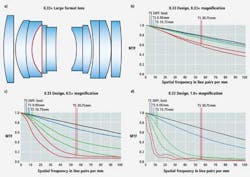
To do so, a lens can be designed so that the spacing between elements or groups of elements can be adjusted. When the spacing is adjusted the design is changed slightly and performance can be increased for a desired magnification and working distance. A lens design created for line-scan sensors, for example, may have a specific magnification associated with it, in this case 0.33x (Figure 1a). On a camera with a 60mm line scan array this will yield a field of view of 180mm.

Lens performance can be analyzed by referencing its modulation transfer function (MTF) curve that allows resolution and contrast performance to be evaluated at a variety of frequencies denoted in line pairs/mm (Figure 1b). This shows the associated MTF curve of the lens at 0.33x magnification. The higher the line pair value, the higher the resolution the system can achieve. In this example curves will be shown reflecting the resolution capabilities of a 12k line scan sensor with 5 micron pixels. This produces an upper limit of 100 lp/mm. A line pair/mm is simply how many sets of 2 pixels there are in 1mm.Two pixels are the smallest sample set that candistinguish the separation between information created by a lens. In this example 1 line pair equals a total space of 10 microns (2.5 micron pixels) and there 100 sets of 10 microns in 1mm. Thus 100lp/mm is the limiting resolution of the camera.
The curves show performance at a number of different positions across the sensor. The black curve shows the diffraction limit of the lens which is the highest performance that the lens can theoretically achieve. The blue line shows the real performance of the lens in the center of the sensor while the red lines show the performance at edge of the sensor (the edge of the field of view). The green lines show an intermediate position on the sensor. Two green and two red lines are shown that highlight the resolution along saggital and tangential lines from the center of the lens since some aberrations can cause asymmetric effects that result in different resolution measurements in different directions.
While not achieving the theoretical maximum performance, the performance of the lens is still good across the sensor. If the lens is then moved to a closer working distance to reduce the field of view and achieve a higher magnification, the performance of the lens will be altered. In Figure 1c and 1d MTF curves for magnifications of 0.5x (120mm field of view) and 1.0x (60mm field of view) are shown and, as can be seen, this results in a lower level of performance.
To overcome this, the spacing between lens elements can be adjusted. Figure 2a shows the optical layout for the same lens system but adjusted for 1.0x. The difference in spacing between the lenses elements marked in red between Figure 1a and 2a - essentially changes the thickness of an air lens – and allows performance to be optimized for different magnifications.
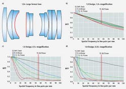
Figure 2b shows the MTF performance of the lens at a 1.0x magnification. Notice the extreme difference in performance between Figures 2b and 1d. Both of these lenses use the same elements, and were designed simultaneously but making a spacing change results in a huge difference in performance. Figures 2c and 2d show the MTF of the 1.0x lens design at 0.5x and 0.33x respectively. Again, a rapid change in performance can be seen as the ideal 1.0x magnification is changed.
This hybrid approach allows for a number of applications to be solved more effectively because it yields better performance than a single lens designed to address multiple applications. Using this approach, two to as many as nine options or more for any given lens design can be achieved to increase system performance. Thus, off the shelf solutions are more available at more palatable price than custom solutions.
While this hybrid solution increases performance it has its drawbacks. First, it will still not achieve the full performance levels of custom solutions targeted for one working distance and magnification. Furthermore, as pixels become increasingly smaller, it will not become any easier for the optics to meet system requirements. Secondly, such hybrid lenses will suffer rapid performance changes similar to a narrowly design specific lens solution. Thirdly, if the lens is not used very close to its designed magnification undesirable results will be seen. Lastly, such lenses will cost more than general purpose lenses and, since such hybrid approaches result in a number of different lenses that all need some amount of specific materials for each lens, there is increased touch to time build all the specific magnifications, and it may be necessary to use large complicated mounting focusing accessories to make the sensor/lens system operate as required.
Greg Hollows, Director of Machine Vision Solutions, Edmund Optics (Barrington, NJ; edmundoptics.com)
Vision Systems Articles Archives