Remote Vehicles Image Ocean Depths

Image courtesy of National Oceanic and Atmospheric Administration/Department of Commerce |
Ron Voerman
Deep water is one of the most challenging environments in which a vision system must operate. Every 10 m systems are deployed below sea level results in an additional atmosphere in pressure. As a result, off-the-shelf vision systems are unable to cope, and specialized housings, connectors, and interfaces for the cameras, lighting, and associated electronics are required. Pressure aside, the cameras used in a deep-water vision system must operate at low light levels.
To develop such systems, the cameras, the modules they are housed in, and their connectors must be chosen to operate in harsh conditions. Undersea vision systems must also be remotely controlled and image data streamed to the surface. As such, custom interfaces—rather than off-the-shelf interfaces such as USB, HDMI, and GigE—must be used.
MacArtney Benelux, a subsidiary of Danish system integrator and cable/connector manufacturer MacArtney Group, has developed a series of subsystems that can be configured to fit onto remotely operated vehicles (ROVs) that operate at depths of 4000 m below sea level.
Rugged cameras
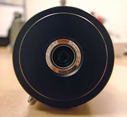
A series of camera modules—called LUXUS—have been developed to operate at these depths (see Fig. 1). These modules house either H11 or FCB-EX20D/P block cameras from Sony. Capable of capturing images at HD resolutions with a viewing angle greater than 50°, they operate in light levels as low as 0.25 lux. To ensure that they operate at pressure, they are placed inside protective waterproof, cylindrical titanium housings.
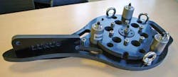
To enable the cameras to capture undersea images, the field of view of each camera is lit using Bridgelux LEDs positioned on a mechanical plate together with the cameras. This lighting illuminates the area up to 10 m in front of the cameras (see Fig. 2).
Aside from capturing images, ROV systems must be fitted with other types of sensors. Clusters of sensors housed in a single unit continuously measure the conductivity, depth, and temperature (CDT) of the water. These physical parameters are correlated with captured images to measure the distribution and variation of organisms in the ocean. Onboard sonar systems perform obstacle avoidance or recognition of specific undersea targets such as mammals.
From the surface
Because of the depths at which systems must operate, an innovative approach was taken to control and power the sensors fitted to the ROV and transferring data to the surface. To ensure that the control signals to the cameras, lighting, CDT sensor array, and sonar can be transmitted to a depth of 4000 m or more, the system uses a topside PC-based control unit, also known as the LUXUS. This PC allows sensors to be activated or deactivated, the brightness of the lighting to be remotely adjusted according to silt levels and resulting visibility distances, and the zoom and the iris of the camera to be manipulated.
To control the underwater sensors, USB signals from the PC-based unit are converted to RS-232 signals using a USB-to-RS-232 serial line from Moxa. RS-232 control signals from the PC are then multiplexed using a NEXUS multiplexer from MacArtney and electro-optically converted to fiber-optic signals. These signals are then transmitted via a fiber-optic cable to a second subsea NEXUS multiplexer using an RS-232 serial protocol. The subsea unit demultiplexes the optical control signals from the surface unit and converts them into electrical signals before passing the control data to the sensors, cameras, CDT, and sonar equipment over an RS-232 or Ethernet interface.
Inside each of the two cylindrical titanium housings that contain the Sony block cameras, a PCB converts the RS-232 control signals from the undersea multiplexer to a set of Sony VISCA (Video System Control Architecture) commands. These are relayed to the IFBE232-SDI HD/SDI interface board on the Sony cameras to allow zoom, iris, and focus of the cameras to be controlled remotely from the surface. While the intensity of the LED lights is controlled in a similar fashion, the CDT and sonar equipment is controlled over dedicated Ethernet interfaces from the multiplexer unit.
Both the data and control signals are multiplexed using coarse wavelength-division multiplexing (CWDM). The technique of employing separate wavelengths to encode data from each of the sensors and cameras effectively increases the rate at which data can be transmitted from the ROV to the surface.
To the surface
The same electro-optical conversion technique is employed to transmit data to the surface from the cameras and sensors. Here, data from the undersea sensors are transmitted to a subsea multiplexer over an RS-232 or Ethernet interface where they are converted to multiplexed optical signals before being transmitted to the topside multiplexer (see Fig. 3).
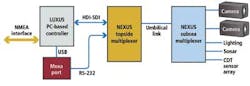
Image data from each of the Sony cameras are output over an HD-SDI interface and converted into RS-232 signals by the control boards in the cameras before being transmitted to the subsea multiplexer. Multiplexed data from the cameras and other sensors are then relayed to the surface over the fiber-optic cable. Once there, the rack-mounted NEXUS demultiplexes the signals, separating the signals from the cameras into their constituent HD-SDI video streams.
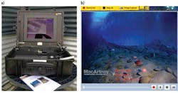
Video data are then passed to the LUXUS Windows-based control unit that enables the video output of the cameras to be viewed on a 17-in. monitor (see Fig. 4).
The LUXUS control unit also sports a National Marine Electronics Association (NMEA) interface—a communication specification commonly used on ships that defines how various pieces of marine electronic equipment communicate. Using this interface, a GPS system can be connected to the LUXUS control unit to enable subsea image and sensor data to be displayed along with the location of the vessel.
Ron Voerman is managing director at MacArtney (Hoogvliet, the Netherlands; www.macartney.nl).
Company Info
Bridgelux
http://bridgelux.com
MacArtney
www.macartney.nl
Moxa
www.moxa.com
Vision Systems Articles Archives