INDUSTRIAL INSPECTION: Laser-based vision system ensures accurate welding
Many of today's automotive components must be properly assembled into sub-components before they can be installed. Manufactured from multi-layer plastics, these components often have complex geometries that make manual assembly difficult. Rather than perform these tasks manually, companies such as BF-Maschinen (Geretsried, Germany;bf-maschinen.de) manufacture systems to perform these tasks.
To assemble gas tanks and fuel filler hoses, for example, the company has developed a system that automatically performs the task of welding the two plastic parts together. To perform this task, each individual part is heated, pressed together and then allowed to cool.
"However," says Dr. Simon Che'Rose, Head of Engineering at Framos (Pullach, Germany;www.framos.eu), "if the two parts are improperly aligned, the resulting joint will not be properly welded and may result in a leaky fuel system." To ensure that the two parts are properly aligned, BF-Maschinen tasked Framos to develop a machine vision system that could accurately determine the alignment of each part before welding and image the results of the finished fuel sub-system.
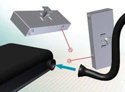
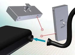
"As each part enters the automated assembly system," says Che'Rose, "the plane of both the inlet to the gas tank and the fuel filler hose must be in parallel to ensure a perfect weld." Thus, the orientation of each part must be accurately measured. To accomplish this, Framos has developed a structured laser light-based vision system that employs a Smartek (Cakovec, Croatia,www.smartekvision.com) GC1391 1.3 Mpixel Gigabit Ethernet CCD camera and a laser line projector from Z-Laser (Freiburg, Germany; http://z-laser.com).
In operation, a laser light cross is projected onto the image of both the inlet to the gas tank and the fuel filler hose by using two such systems. Because the camera and laser are calibrated with respect to each other, the reflected laser image can be used to measure the orientation of each part.
"If, for example, the imaging system were mounted horizontally to the plane of the part," says Che'Rose, "then the reflected orientation of laser light from a perfect aligned plane would appear as a cross oriented in the same direction."
Of course, in practice, the imaging system must be mounted at an angle to both the gas tank and the fuel filler hose. However, because the laser and camera system are pre-calibrated, any deviation from perfect part alignment can be used to calculate the orientation of both the tank and hose.
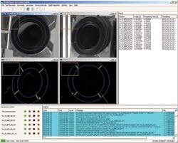
To perform this task, reflected laser light images are transferred to a host PC and, the orientation of the part compared with known good orientation measurements and the degree of tilt of the flange plane measured. Software to perform this task was written by Framos in C++. Should either part be out of alignment, the PC instructs a PLC to halt the machine. If this is the case, either the tank and filler hose are removed and the machine restarted.
As well as performing a check on the orientation of each part, the system checks whether each part has been properly heated, prior to welding. After reflected laser light images are transferred to the PC, the tank and hose are illuminated with LED light and each CCD camera transmits visible light images to the host CPU. Both sets of images are then displayed on a GUI.
"If a part has been properly heated," says Che'Rose, "the liquid plastic surfaces of the tank and hose will reflect a large amount of light allowing the operator to check whether the heating process is performing correctly." After parts are welded together, the finished welded joint is again imaged by a Gigabit Ethernet camera using one of the laser-based vision systems and by a third Gigabit Ethernet camera positioned diametrically opposite. In this way, an approximate 360o view of the welding surface is also captured.
Vision Systems Articles Archives