Chris Hammond, Embedded Systems Engineer, Pratt & Miller Engineering, New Hudson, MI
Endurance racing is a challenging task for even the most experienced of drivers. They must drive at the limits of their car for extended periods and race during the day and night, often in adverse weather conditions, such as rain and fog.
During these races, it is difficult for drivers to gauge the number, speed and location of vehicles behind them. Unless they monitor their rear view mirror continuously, they may be unaware of other vehicles approaching them or about to overtake them. Dividing their attention in this way can be an arduous task, especially when driver fatigue begins to set in.
Recently, rear-view cameras and cockpit mounted displays have been deployed on vehicles to provide drivers with a more comprehensive view of the cars following them. Unfortunately, such cameras have severe limitations during night time driving, and when covered in water, dirt or mud, the images on the display can appear washed out or blurred.
The need for a better solution was felt especially sharply by Pratt & Miller Engineering's (New Hudson, MI, http://prattmiller.com) Corvette Racing Team at the 24 Hours of Le Mans in 2010.
They were leading their class, approaching a very technical part of the track at 140 mph when a faster Prototype-class car overtook unexpectedly for an inside pass. The Corvette was suddenly forced to the outside, lost grip and slid rear-first into a barrier. The crash and time lost in the garage took Corvette out of contention for a podium finish (see http://bit.ly/16Evmyf).
To address these issues, Pratt & Miller Engineering has developed a collision avoidance system that combines radar and vision to enable drivers – whether endurance racing or not—to visualize events behind their cars at a glance, even under appalling weather conditions.
Collision avoidance
The collision avoidance system comprises a custom-built unit that houses a radar sensor and a machine vision camera. Mounted on the rear of the car, the unit communicates radar and visual data to the display, a custom-built Linux PC with integrated LCD screen that resides on the dashboard inside the vehicle (Figure 1).

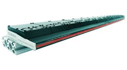
The Bosch Automotive Technology (Leonberg, Germany; www.bosch-automotivetechnology.com) long-range radar sensor used in the system is a modified version of a product currently used in Bosch's active cruise control system for high end vehicles.
The radar sensor detects objects and measures their velocity and position relative to the movement of the host radar-equipped vehicle. To do this, the sensor has four antenna elements that simultaneously transmit radar waves in the frequency range between 76 and 77 GHz. These waves are reflected by objects behind the vehicle.
By comparing the amplitudes and phases of the signal echo received by the antenna elements, conclusions about the objects' position can be drawn. The relative speed of objects is measured using the Doppler effect and the distance to the object can be determined by the time delay between the transmitted and received radar signals.
While the commercial production radar only delivers data on the location and relative speed of a single vehicle, the motorsports version of the radar used in the Pratt & Miller system can track the position, relative velocity and lateral offset of up to 32 cars at a range of up to 60m with a 10Hz update rate.
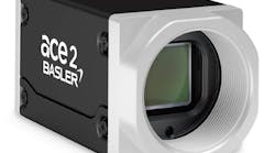
The Bosch radar system is mounted in a custom built bracket together with a 1024 x 600 GigE 5240RE machine vision camera from IDS Imaging Development Systems (IDS; Obersulm, Germany, http://ids-imaging.com) that simultaneously captures images of the cars behind the vehicle at 30 fps. The 5240RE camera was chosen for the collision avoidance system due to its ruggedness, low latency and global shutter.
Thanks to its IP65/67 rating, the 5240RE machine vision camera is dust tight and protected against water ingress, enabling it to operate for 24 hours at a time while subjected to 4-5G loads and exposed to conductive brake dust and wet conditions.
The latency - or the time delay between capturing an image and displaying it on the screen of the PC display - was also a significant factor behind the choice of camera. By using the GigE-based 5240RE camera at 30fps, a latency of about 50 ms was achieved, enabling the current state of the vehicles following the car to be displayed on the screen in real time.
Because the camera was required to capture images of rapidly moving objects while subject to 4-5G vibrations, a camera operating in a rolling shutter mode could not be used. Instead, the 5240RE camera is used in a global shutter mode, eliminating the rolling shutter artifacts by simultaneous capturing entire image frames at a time.
Once captured, data from the machine vision camera are transferred over a GigE interface to the Intel Core i3 Linux PC-based display unit, while a separate CAN (Controller Area Network) bus is used to transfer data to the PC from the radar sensor (Figure 2). In addition, the wheel speed and the rotational velocity of the car - or yaw rate - from a sensor and a gyro on the vehicle are also transferred to it over a second CAN bus interface.

The position of the switches on the dashboard used to control the instrument panel dimmer are also transmitted to the PC over the same CAN bus interface, so that when a driver turns down the brightness of the instruments at night, the PC display responds in a similar fashion.
Colored chevrons
A Python program running under Linux on the PC interprets the relative speed data from the radar sensor and the wheel speed data from the driver's car to calculate the absolute speed of the cars behind it. This data - together with the position and acceleration data from the radar sensor is used to calculate the size, shape, position and color of colored chevron indicators that are overlaid onto the image from the machine vision camera on the LCD display.
The chevrons indicate the speed, distance and lateral position of the cars following the vehicle (Figure 3). To achieve an intuitive interface, the chevrons are drawn in 3-D space and then transformed into pixel values using a calibrated camera model. The result is a "video game style" augmented-reality display where the chevrons appear to actually hover in space above the cars. Thus, the markings can be immediately understood with no special training, and more importantly, with minimal attention removed from driving.

Their colors range from red to yellow to green - a red chevron provides an indication that a car is approaching quickly, a yellow chevron shows that the speed of the two cars are identical, while a green chevron shows that the car is falling back. Since the chevrons are drawn in 3-D, their sizes highlight the distance that each car behind is following.
In addition to displaying the distance and speed of each following vehicle, the system can also determine and then highlight on a gauge at the side of the display exactly how far back the cars behind are in seconds, important data for racing drivers to gauge their performance.
Because the data from the radar is acquired at a rate of 10Hz, the relative speed, distance and offset data acquired by the radar may not be acquired at a fast enough rate to enable the system to update the size, color and position of the chevrons on the display in real-time when a car is cornering quickly.
To compensate, the system incorporates wheel speed and yaw data from the wheel sensor and gyro into a Kalman-style filter together with the most recent estimates from the radar sensor to predict what the most likely position and size of the chevrons on the display would be during that time. The effect is that the driver is always provided with an accurate, smooth indication of the speed and distance of the following vehicles.
The system's other primary feature is to display a large flashing arrow whenever another car attempts a passing maneuver, grabbing the driver's attention and indicating which side he is being passed on. The color of that arrow - which also ranges from red to yellow to green - also indicates the passing car's closing speed (Figure 4).

Where the system really comes into its own is at night or during adverse weather conditions. Normally, a driver would see very little in a rear-view display at night, but with the addition of the radar data, complete details on the cars behind can be provided (Figure 5).

When it is raining or there are wet conditions during a race, a rear view camera can become covered in water, dirt or mud. If it does, it will often become difficult to discern the status of the following cars from the images on the display. Thanks to the data acquired by the radar sensor, however, drivers have a clear indication that there are cars behind them and their distance.
In many endurance races, GT class Corvettes race with prototype class cars which are considerably faster, a fact that has led to many collisions on the track. But because the collision avoidance system can calculate the acceleration of the cars behind it, it can determine whether they belong to a faster class of vehicle. If they do, the system highlights this to the driver by displaying a cross through that vehicle's chevron indicator, so that the driver can be ready for a forthcoming pass.
If the camera should malfunction or become damaged during a race, the software can use data from the radar sensor to reconstruct a 3-D wire model of cars that are then overlaid onto the display. Hence, even if there is no camera feed, a driver can visualize the location, distance and speed of the cars behind (Figure 6).

The system also records video in real time on a 240GByte hard drive in the PC. After a race, videos can be downloaded from the system to a PC over a USB port where they can be analyzed to review the performance of the system and the driver. Code changes can also be tested against a playback of these log files to ensure proper operation during the scarce track time available.
The system made its debut at the 2013 12 Hours of Sebring, an endurance sports car race held on March 16, 2013 at the Sebring International Raceway in Florida. There it was proven to give drivers a wealth of information while requiring a fraction of the attention time that is needed when using a traditional rear-view mirror. One of Pratt & Miller's two Corvette Racing C6.R's equipped with the new radar system won first place in the GT class, and neither car suffered any passing-related incidents.
Company Info
Bosch Automotive Technology
Leonberg, Germany
www.bosch-automotivetechnology.com
Imaging Development Systems GmbH
Obersulm, Germany
ids-imaging.com
Pratt & Miller Engineering
New Hudson, MI, USA
http://prattmiller.com
Vision Systems Articles Archives