FACTORY AUTOMATION: Embedded vision system targets assembly line inspection

In many factory automation systems, it is necessary to sort good products from bad as they pass along a conveyor. In the simplest of these cases, an encoder is used to track the position of the part along the conveyor and a proximity sensor used to detect the presence of a part at a specific point. The output from the proximity sensor is then used to trigger a camera. Camera data are then transferred to a host computer and the image of the part analyzed for any specific defect. Should a defect occur, an output from the PC may be sent to a PLC that in turn controls a rejection mechanism to eject the part.
To perform this task, the host PC must keep track of the encoder count when the camera is triggered. If the part fails the inspection, the CPU then adds an offset to the encoder to account for the distance between the camera trigger and the ejection trigger mechanism. This value is then sent to the PLC so that the PLC triggers the rejection mechanism at the correct point on the conveyor line.
Rather than use a CPU to perform this task, many systems integrators turn to embedded machine vision systems. Featuring support for multiple cameras, PC-based processing, vision software and I/O support, these can be used as low cost replacements for PC-based systems. While such systems may appear simple, they can become increasingly more difficult to engineer if parts needed to be classified and binned using multiple rejection mechanisms.
As Brad Buchanan, Senior Software Engineer in the Vision Research and Development Group of National Instruments (Austin, TX; www.ni.com) points out, using the CPU to perform the task of tracking the encoder, adding multiple offsets and I/O tasks can add a considerable amount of latency and jitter to such systems, decreasing their throughput and reliability.
To overcome this, an FPGA can be used to perform these tasks. Indeed, this is just one of the motivations behind the company's latest Compact Vision System, the soon-to-be-announced CVS-1457RT real time computer vision system and its PC-based add-in board equivalent, the PCIe-8237R. With two PoE Ethernet ports, 8 isolated inputs and outputs, 8 bi-directional TTL lines and two RS-422 encoder lines, the CVS-1457RT closely couples its on-board Intel Atom 1.66 GHz processor with an FPGA, allowing I/O functions to be performed using the FPGA thus reducing system latency and jitter. The FPGA can respond to inputs by driving an output line within 20ns, which is far better than a CPU could achieve due to software delays. Better still, such an approach can eliminate the role of the PLC in vision systems that may coordinate only a few rejection mechanisms.
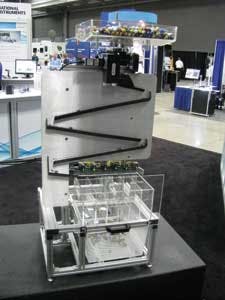
To demonstrate the power of the concept, Buchanan and his colleagues showed a demonstration system that used the CVS-1457RT to sort colored marbles. First shown at August's NIWeek 2013, the system consists of a hopper of six different colored marbles that are gravitationally fed down a slide. As they traverse the slide, a proximity sensor interfaced to an ISO line of the CVS-1457RT is triggered and an "Action Command" GigE Vision packet is sent over the GigE interface to an acA645-100gc camera from Basler (Ahrensburg, Germany; www.baslerweb.com). Color classification of the image of each marble is then performed in HSL color space using NI Vision Development Module running on the unit's Atom processor.
If the marbles were moving along a conveyor, an offset could be added to the camera trigger from an encoder to account for the time taken to travel to one of six independent ejector solenoids. However, in this case, the marbles are gravity fed down a slide and the time required to reach a specific position on the slide may vary, so each ejector has a proximity sensor mounted directly over it.
After the color of each individual part is determined by the application running on the CPU, the application will add a pulse item to the corresponding FPGA queue of the correct ejector, and empty pulse items to all the previous ejector queues to allow the marble to roll past them without being ejected. The FPGA – not the CPU - maintains a queue for six ejector solenoids located at the bottom of the slide.
Once there are items in the FPGA queue, the FPGA monitors the proximity sensors to determine when the marble is in front of each ejector and removes an item from the queue when the proximity sensor detects an object. If the item is a pulse, it will cause the marble to be ejected. If the item is an empty pulse, the marble will roll past and the FPGA will start waiting for the next marble to roll past before it removes the next item from its queue. I/O from these sensors and ejectors are wired to 6 Isolated Inputs and 6 Isolated Outputs on the CVS-1457RT.
Vision Systems Articles Archives