Medical Imaging: Micro-tomography system generates 3D images of teeth

Tooth decay is often revealed by an X-ray taken in the dentist's chair. The image taken is relatively coarse and only reveals the presence of the problem, what it does not show is detail about the mechanism that has led to the decay. Understanding the processes that occur during tooth decay and indeed repair involves studying the concentrations of minerals such as calcium present in the structure.
X-ray micro-tomography is now helping researchers at Queen Mary University of London (QMUL; London England;www.qmul.ac.uk) gain a deeper understanding of these underlying processes by generating high-resolution images that can detail these mineral concentrations. Image generation involves scanning the tooth using X-rays over an extended time period.
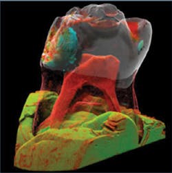
In the research, performed by Dr. Graham Davis, a Reader in 3D X-ray Imaging at the School of Medicine and Dentistry at QMUL, micro-tomography is combined with the long X-ray exposure of extracted teeth to enhance as much as possible the contrast of the image. The resulting pseudo-colored 3D model reveals details of both the structure and density of the tooth.
These 3D models are reconstructed from a series of 2D X-ray images. To capture these 2D images, a tooth is first placed on a rotating platen and X-rays from an XT H 225 micro-focus X-ray cone source from Nikon Metrology (Tring, Hertfordshire, England;http://nikonmetrology.com) that is used to radiate the tooth. Attenuated X-rays are then captured by a 4k x 4k CCD-based 800S X-ray camera from Spectral Instruments (Tucson, AZ, USA; www.specinst.com).
To convert the X-rays to photons, a Thallium doped Caesium Iodide scintillator from Applied Scintillation Technologies (Harlow, England;www.appscintech.com) is bonded to a fiber optic faceplate from Incom (Charlton, MA, USA; www.incomusa.com) that is then fitted to the face of the CCD camera.
Before scanning, however, the tooth must be correctly placed in the X-ray beam of the imaging system. To do so, two M-500 series linear stages with recirculating ball guides from Physik Instrumente (PI; Karlsruhe, Germany;www.physikinstrumente.com) are used in conjunction with the company's C843 PCI controller to position the rotary table at the correct height and in focal path of the imaging system. A PRS-110 rotary stage, also from Physik Instrumente is then used to control the rotary stepping of the stage.
While 2D images could be captured by simply exposing the camera while the tooth is revolved around its axis, this is not the case in the system designed by Davis and his colleagues. "Since every pixel in the CCD sensor will have its own (albeit minor) difference in sensitivity," says Davis, "3D reconstructed images of the 2D data sets captured after multiple rotations, will exhibit errors that will appear as rings in the reconstructed image."
To eliminate these ring errors, the X-ray system employs a novel use of time-delay integration (TDI) in which, at every rotary position, the camera is moved across the field of view of the sample under control of a third M-500 linear stage. As the camera moves, the camera is read out in 2 x 2 binned mode to yield an image that is 2k pixels high and as long as required to image the specimen or the width of the X-ray field allows. This image is then transferred to a host PC over a fiber-optic cable (via a labyrinth through the X-ray shielding) using Spectral Instruments' proprietary PCI interface board. Once captured, alternate 2k columns are again averaged, resulting in a 1k x 1k final image. Averaging the CCD pixels in this manner then eliminates the ring artifacts when image reconstruction is performed.
As the specimen is rotated through 360°, the camera is moved backwards and forwards across the field of view and images are transferred to the PC. Image reconstruction is then performed on the complete set of 2D images using a back-projection algorithm first developed by Feldkamp, Davis and Kress (http://bit.ly/1yxZAEE).
Grey levels of the 3D reconstructed image can then be pseudo-colored to identify the density at any given point and show various aspects of tooth decay. In the image shown, for example, the blue coded area highlights a lesion in the tooth where decay (loss of calcium is present). As can be seen, the red area shows pulp that is retreating from the area of decay, showing how dentine is being formed to protect the pulp.