Lenses, lights, camera and action: Applying cinematography lessons to machine vision systems

On a motion picture set there may be three or more cameras imaging the same scene from different angles. In such scenarios, it is vitally important that the lighting appears uniform. Thus, when cinematographers specify lenses for a motion picture scene, they must ensure that when multiple cameras are used, the same amount of light will be exposed on the film or digital imager of each camera.
However, setting the same aperture (or f/stop) of each lens to a similar setting is not sufficient since the aperture number of the lens alone cannot guarantee that the same amount of light – even with lenses of the same focal length – will ensure this uniformity. To do so, cinematographers use lenses marked with transmission (or t/stops) rather than f/stops. While directly related to f/stop, lenses specified in t/stops take into account the measured on-axis light transmission for a particular lens even when lenses of different focal lengths are used to image a scene.
Numerical aperture
To appreciate this, it is necessary to understand lens parameters such as Numerical Aperture (NA), aperture and transmission stops and how they are related. Although not a commonly used term in the machine vision and robotic vision fields, the NA of a lens is well known in astronomy, microscopy and fiber optics communities where f/numbers and t/stops are not used. However, it is important to understand this NA value to appreciate the importance of f/stops and t/stops in imaging applications.
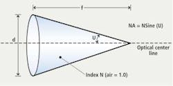
In microscopy, objective lenses are marked with their focal length, power (magnification) and NA values. This NA value provides the systems developer with a numerical value that specifies a measure of the ability of the lens to gather light and to resolve fine specimen details while working at a fixed object distance (Figure 1).
Angular aperture (2U), which varies with the objective's focal length, is the maximum angle of image-forming light rays emanating from the specimen or sample imaged by the lens that the objective can capture when the specimen or sample is focused. The NA of the lens from Figure 1 is given by NA = N Sine (U) where N is the index of refraction – a dimensionless number - that describes how the light propagates through the medium. Thus, the numerical aperture is limited by the angular aperture and by the imaging medium's refractive index. If an image is formed in air, and U is 20 degrees then NA = 1 x Sine (20 degrees) = 0.342 since the index of refraction will be unity.
Open wide
Numerical aperture is an important lens parameter to understand since it is directly related to the focal length stop (or f#) of the lens. From Figure 1, it can be seen that
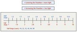
Since the focal length stop (f#) is a ratio, the final value is dimensionless. For example, a lens with a focal length of 100mm and front glass aperture of 50mm would have an f/# = 100/50 = 2.0. Machine vision lenses use adjustable apertures that – for any specific lens – can be adjusted to vary the amount of light appearing at the focal plane of the imager. While increasing the aperture one full stop, for example, doubles the amount of light transmitted by the lens, reducing the aperture one full stop has the opposite effect (Figure 2). Image stop size is also one factor that affects depth of field. Smaller stops (with larger f# numbers) produce a larger depth of field, allowing objects at a range of distances to be in focus simultaneously.
In optical terms, the lens aperture used to calculate the numerical aperture (f/#) of the lens is called the entrance pupil diameter—note that this is not the diameter of the front glass optical element of the lens (Figure 3). The entrance pupil position and size in a lens are calculated by ray tracing, and are typically provided as part of the lens specification. The optical stop of a lens is where the designer places the iris, since both on and off-axis rays at this position are equally impacted by changing the iris diameter. That is, the relative light level of the entire image is uniformly brightened or darkened as the iris is opened or closed.
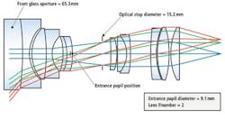
From Figure 3, it can be seen that, the "true" f# is given by the ratio of the focal length to the entrance pupil diameter. Thus, the f# of the lens is 18.5/9.1 = 2.0. Using the front glass diameter to calculate the f/# would result in a value of 18.5mm/65mm or 0.28, which is clearly incorrect.
Light transmission
Lenses used by cinematographers are not marked with f/numbers but rather with transmission stops (or t/numbers). While the t/stops value is directly related to the f/stop value, the t/stop takes into account the measured on-axis light transmission for a particular lens. Mathematically, this can be expressed as t/stop = f/# /SQRT (T) where T is the light transmission efficiency (transmittance) of the lens.
Consider, for example, two 100mm focal length lenses with an f#/2.8. One would expect both lenses to transmit the same amount of light based solely on the fact that they have the same f/# numbers. However, this is not always the case since there are other factors that can result in imaged light levels being different in these two lenses.
Glass types used in each lens with differing absorption characteristics can influence the amount of light a lens can pass, as does the number of glass elements, the quality and type of any anti-reflection coatings and any induced vignetting by the lens designer.
For a 100mm f/2.8 lens with six glass elements and antireflection coatings, there will be twelve glass surfaces. While a typical high quality multi-layer coating will reflect approximately 0.5% per surface at the glass air interface, the first order transmission of the lens (or the amount or light through each glass to air or air to glass interface raised to the power of the number of surfaces) will result in:
Since the value of 1 represents a perfect transmission (excluding glass light absorption).
This results in a t/number of 2.9.
For a 100mm f/2.8 lens with ten glass elements and thus 20 glass surfaces and standard single layer antireflection coatings, there will be twenty glass surfaces and if the coating reflects approximately 1.25% per surface at the glass air interface, the first order transmission of the lens will be:
This results in a t/number of 3.2.
Thus, two lenses with the same focal length and numerical aperture do not necessarily transmit the same amount of light.
In general t/numbers are close to their f/number values but can vary greatly with zoom lenses. Cinematographers find t/number advantageous over f/numbers since using t/numbers ensures multiple cameras will image the scene in the same way even if different focal length lenses are used.
Since t/numbers values are independent of focal length they can be useful in machine vision systems that employ more than one camera/lens system. By having the lenses all set to the same t/number via the aperture ring, the same illumination level will appear on the camera film or image sensor.
Lens manufactures that produce lenses for cinematography calibrate their lenses during manufacturing will engrave the t/number values on the aperture (iris) ring where typically the f/number values would be found for traditional machine vision lenses. However, lenses calibrated in f/numbers can also be calibrated on a t/stop bench and the t/numbers added to the aperture ring. In the machine vision industry, it would be a significant step forward if lenses featured both f/stops and t values - especially for those building multiple systems or using multiple cameras in such systems.
Stuart W. Singer, Vice President and Jim Sullivan, Director of Industrial Optics, Schneider Optics (Hauppauge, NY; www.schneideroptics.com)
Vision Systems Articles Archives