Vision system inspects bottle caps at high speed
Andrew Wilson,Editor
Consumer products such as plastic bottles and containers of bleach, detergent and food require caps that will ensure that – once they are fitted – no spillage will occur. To accomplish this, manufacturers of plastic caps produce such caps with internal liner materials made of foam or paper with foil surfaces. During the lining process for plastic caps, sometimes hot melt glue is first applied to insure that the liner stays in the correct position.
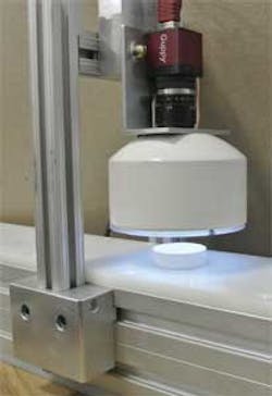
"Because these caps are manufactured at rates that often exceed 1,000 parts/min," says Joseph Gochar, President of Logical Systems (Woodlawn, MD, USA;www.lsiofmd.com), "manual inspection of each cap is not possible." To automate this process, Gochar and his colleagues have developed a system that uses a combination of custom LED lighting, off-the shelf-cameras and software combined with a patented conveyance mechanism (Figure 1).

While the system must accurately detect whether the liner has been properly placed within the cap, it must also detect if the liner is centered and whether any short shot conditions exist. As well, should the system detect any glue that may be present on the threads of the cap, the part must be rejected since, if such defects occur, the cap will not properly attach to the bottle or carton later in the manufacturing process.
"Since the glue that is added to the cap is clear," says Gochar, "it is difficult for the human eye to discern whether the glue is present on the cap threads." However, by adding an ultraviolet (UV) dye to the glue and illuminating the cap correctly, the fluorescence of the glue will reveal the presence of the glue on the threads."
Patented motion
As caps exit a lining machine, they are conveyed onto a rotary accumulation table which in turn feeds them single file to a linear belt conveyor. The main purpose of the belt conveyor is to control the pace at which caps are presented to the vision system. So that each cap can be accurately inspected by the vision system, each cap must be separated from adjacent caps.
Cap separation for vision inspection has been performed many different ways, but an air slide conveyor/separator approach provides one of the best combinations of features for automated inspection. Logical Systems has developed and patented a novel, more compact method of performing this task (see US Patent US 7800009 B2 athttp://bit.ly/1n81XEP).
The company's air separator conveyor is comprised of an ultra-high molecular weight (UHMW) polyethylene into the top surface of which are formed angled air holes in two rows along the direction of travel. These air holes are placed at an increasingly greater frequency along the air slide slide and blow air onto the part as it moves along thus accelerating and separating each part before it is presented to the vision system (see "Air conveyor separates plastic parts").
Dual illuminators
Because caps can consist of different shapes and colors, a single illumination system does not provide the best lighting for all situations. For example, should a cap be black, light will not pass through. However, such backlighting is effective in obtaining an image that can be used to judge the caps outer diameter and its center. Similarly, while an image obtained by lighting the part with a cloudy day illuminator can reveal much about the internal formation within the cap, the captured image is not as useful for determining the part's dimensions. By illuminating the cap using both a backlight and a dome top light simultaneously, however, significant features of the part are revealed.
Thus, to inspect the caps for correct liner placement, "short shot" conditions, and glue and other defects, the system incorporates both an overhead white LED-based cloudy day illuminator or UV LED array and an IR backlight placed under the UHMW air slide.
As each part enters the machine vision system, the strobes are pulsed using a PCI-CTR05 relay card from Measurement Computing (Norton, MA, USA;www.mccdaq.com) embedded in a host PC (Figure 2). As the strobes are fired, an image of the part is captured by a Guppy FireWire camera from Allied Vision Technologies (Stadtroda, Germany; www.alliedvisiontec.com) and then transferred to the host PC.
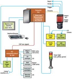
Image inspection
To inspect the images, the PC runs the Sherlock machine vision package from Teledyne DALSA (Waterloo, Ontario, Canada;www.teledynedalsa.com). Using the software's Spoke tool, the software finds the outside edges of the parts in the image and calculates its center and shape. Should any of the spokes not find an edge due to dirt or dust on the lens of the camera system for example, the part is then flagged as bad.
To inspect whether the liner of each cap is correctly placed and not damaged, a circle tool within Sherlock is used. Placed within the cap region, this single pixel wide circle is used to measure the grey scale values of each pixel and compare this with known good values. Should a defect such as a cut liner appear in the image, this will result in an out of tolerance error and the part will be rejected.
Similarly, to inspect for any excess glue that may appear on the cap threads, another circle tool is used. Should any glue be present, the resulting image will contain bright areas where the glue has fluoresced (Figure 3). Should this occur, the returned values from the circle tool will be higher than expected and the part is then rejected.

"Since manufacturers of plastic caps make parts of different sizes, shapes and colors," says Gochar, "it was necessary to choose a vision software package that could be adapted quickly. This can be accomplished readily using the vision tools within the Sherlock software package." Parameters for each cap part number can then be stored and recalled as required. Interfacing this software with a user-friendly human machine interface (HMI) written in Microsoft Visual Basic allows the operator to select the required part number without requiring machine vision programming.
Rejection mechanisms
After each part is inspected and a pass/fail decision made, the system rejects bad parts as they exit the inspection station on the air separator conveyor. Should a part be defective, a reject signal is sent from the camera to a DL-260 programmable logic controller from Automation Direct (Cumming, GA, USA;www.automationdirect.com).
The PLC generates a 15-20ms pulse that actuates a MAC 35 series direct solenoid operated 3-way poppet valve from MAC Valves (Wixom, MI; http://macvalves.com) that has an air nozzle directed to blow the defective part from the conveyor.
Air conveyor separates plastic parts
By Joseph Gochar, President, Logical Systems
To provide a means to present plastic caps to a vision inspection system, Logical Systems, has developed a patented air separation slide (US patent # 7800009 B2). With cap production rates from 800 - 1200 parts/min, sizes ranging from 20-110mm, the design of the slide was required to be as small as possible to conserve factory floor space, and at the inspection point, separate one cap from another.
Because cap inspection required a backlight, it was important that the top surface of the air slide allow for light transmission. Because of this, the top slide surface was fabricated from UHMW plastic which provided a wear resistant surface that was both translucent and easy to machine.
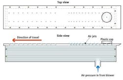
The air slide is designed as an enclosed, air-tight, rectangular box with air jets drilled in the UHMW top surface. By regulating the air pressure in the box, the force of the air jets can be modulated to provide the desired cap speed and separation. In addition, the placement of the air jets were made progressively closer together on the first half of the slide to enhance the differential acceleration of each cap and provide the desired cap spacing.
The end result provides a method to convey and separate caps at speeds up to 1200 PPM while employing no moving parts. Since the top surface is made of UHMW plastic and because the air jets float the caps along, there is very little actual contact between the slide and the caps so that even polished caps are not scratched.
Companies mentioned
Allied Vision Technologies
Stadtroda, Germany
www.alliedvisiontec.com
Automation Direct
Cumming, GA, USA
www.automationdirect.com
Logical Systems
Woodlawn, MD, USA
www.lsiofmd.com
MAC Valves
Wixom, MI, USA
http://macvalves.com
Measurement Computing
Norton, MA, USA
www.mccdaq.com
Teledyne DALSA
Waterloo, Ontario, Canada
www.teledynedalsa.com
Vision Systems Articles Archives
About the Author

Andy Wilson
Founding Editor
Founding editor of Vision Systems Design. Industry authority and author of thousands of technical articles on image processing, machine vision, and computer science.
B.Sc., Warwick University
Tel: 603-891-9115
Fax: 603-891-9297