Stereo vision system inspects reflective tableware
Matti Saarinen
Many stereo imaging systems use two identical cameras that are horizontally displaced such that the image of an object captured by the two cameras overlaps. If a correspondence between points in the two images can then be found, triangulation can be used to determine the depth of the object. The biggest disadvantage of such stereo imaging is occlusion, which occurs when some parts of the scene cannot be seen by one, or both, of the cameras. This is typical when imaging complex objects with cavities and steep edges. In such cases, depth information cannot be obtained from the occluded areas of the scene.
This problem can be partially overcome by using active lighting. In active lighting systems, a projector is used to create an artificially patterned texture on smooth, otherwise non-textured surfaces. However, no matter what imaging method is used, it is virtually impossible to acquire images from objects with glossy, mirror-like surfaces. This task is made more challenging if the glossy object has a high-curvature or an angular surface.
For that reason, many reflective objects - such as ceramic plates, faucets, chrome plated, painted or polished objects - are still manually inspected after they are manufactured. In a typical plate inspection task, for example, both sides of a plate are examined to find cracks, small spots, pores, chips and areas without glazing. The smallest spots - called pin-holes -can be less than 0.1mm in diameter and are difficult to visualize manually. Worse, systems are often required to run at speeds of between 800-1200 per hour leaving less than 5s for an inspector to manually check each product.
Automated inspection
To automate the inspection of such specularly reflective objects, engineers at Helmee Imaging (Tampere, Finland;www.helmeeimaging.com) are developing an inspection station based around an imaging technique called Covered Stereo Deflectometry (CSD) which was invented at the VTT Technical Research Centre (Espoo, Finland; www.vtt.fi) by the company's founders. In a pilot project with BHS Tabletop (Weiden, Germany; www.bhs-tabletop.de), the company aims to prove the technique's effectiveness in detecting defects on a variety of tableware.
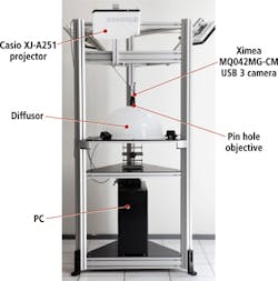
The Helmee stereoscopic CSD inspection station consists of a machine vision system that includes cameras, an illumination system, a PC-based image processing unit, a mechanical frame with dust-proof covers, and an operator interface with monitor and HMI (Figure 1). The image processing software developed to render images from the stereoscopic system is the same for all applications, but the image analysis software must be configured to meet specific customer needs. At present, the company is focused on developing the analysis software to detect defects in ceramic plates from BHS Tabletop.
Helmee's system is based on a triangulation method that enables the system to determine the depth of an object and uses a pattern projector to illuminate a sample with a variety of patterns to create a texture on smooth surfaces. However, the system has been built specifically to image specularly reflective objects. Indeed, the more reflective and curved an object is, the greater the effectiveness of the system.
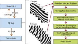
In operation, the system projects a set of sinusoidal fringe patterns onto the surface of an object to be inspected. The phases of the fringe patterns reflected from the surface are then captured by the cameras and used to calculate the 3D location of each point on the surface of the object.
Each item of tableware, such as a plate, is first placed under a plastic semi-transparent dome that is illuminated from above by three XJ-A251 projectors from Casio (Shibuya, Tokyo, Japan;www.casio.com) that each project three 120 degree fringe patterns onto the dome to illuminate its entire 360 degree surface. These fringe patterns vary in longitudinal and latitudinal directions and in phase - to illuminate the plates, five different phases for each direction are used. The longitudinal and latitudinal fringe patterns and five phases are required to ensure that the system software will detect slopes on the surface of the plate in any direction. Separate frequencies of fringe patterns enable the defects on the plates to be imaged at a variety of resolutions.
If there are any variations in the slope of the surface of a plate due to defects, the sinusoidal fringe patterns reflected from those defects will suffer from phase distortion. The greater the variations are, the greater the distortion of the fringes. By capturing images of the distorted fringes and measuring them, it is then possible to calculate the surface normal from each point on the plate.
In operation, fringe images are captured by two MQ042MG-CM 4MPixel (2048 × 2048) USB3 cameras from Ximea (Munich, Germany;www.ximea.com). The cameras image the plate though two pin-hole apertures in the dome to minimize any blind spots that would be created by the use of a larger objective lens. Distortions in the fringe patterns across the entire plate are captured by the two cameras as five raw images. From these, distorted phase maps are then calculated. However, at this stage, the phase maps suffer from phase discontinuities, which produce an unusable wrapped output. To rectify this, the phase discontinuities are first removed by a phase unwrapping algorithm.
Once the discontinuities are unwrapped, the resulting unwrapped phase maps can be processed in software to derive a set of precise coordinates on the surface of the dome from where the light reflected from each point on the surface of the plate has originated. Given the coordinates on the dome and the locations of the light captured by the pixels in the cameras, a surface normal vector field from the plate can then be calculated by triangulation. The process of calculating the normal vector field is essential before a 3D image of the plates can be rendered. Once rendered, however, the image of the plate can then be filtered, segmented and analyzed (Figure 2).
Modular approach
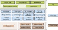
The Helmee system software comprises a set of three layers. One set of software components handles the graphical user interface, enabling an operator to configure the machine to handle a number of different inspection tasks. A second set of system software components are used to co-ordinate the projector and cameras to acquire the sets of images from which the surface model of the object can be calculated and to process and analyze the images. Lastly, a third set of software interfaces the system to external system components such as cameras, conveyors and robots (Figure 3).
This modular approach enables a user to capture an image of a specific item of tableware and, from a recipe editor, select particular regions of interest in the object to be inspected. The user can then specify certain inspection parameters from the recipe editor, such as the size of the defects to be identified in each region of the plate. Having determined these parameters, the recipe manager software determines what frequencies of the sinusoidal fringe patterns need to be generated by the inspection coordinator software to enable the cameras to capture image of the surfaces of the plate at the desired resolution.
The resolution of the calculated 3D image is directly related to the frequency of the fringe pattern used to illuminate the plate. Since higher frequency phases result in higher density phase maps, the system software can resolve very small defects on the plate from them. However, lower frequency sinusoidal fringe patterns and consequently lower density phase maps play an equally important role, since they are more effective at enabling the system software to image defects on the high slopes of the plates.
Consequently, a user may choose to select two or more regions of interest in a plate - one that highlights the central mirrored well of the plate and the other its inward sloping lip. The system will then image the central part of the plate by illuminating it with high frequency fringe patterns, while the lip can be imaged using lower frequency patterns. In this way, the system can resolve defects on both parts of the plate.
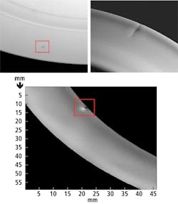
Once grayscale and 3D images of the plate have been produced by the system, defects on the plate are detected using conventional image processing software routines from the OpenCV library. A high pass or Laplacian filter, for example, highlights the location of the defect itself, after which adaptive thresholding separates defects from the background based on the difference in pixel intensities of each region (Figure 4).
Following this, the software calculates the number of defects, their size, shape and location. After this analysis, it can determine whether the plate has passed or failed the inspection task and whether or not it should be removed from the production line. The result is then displayed to the user via the graphical user interface on the HMI.
Speed and accuracy
At the present time, the inspection of plates at BHS Tabletop AG occurs at the end of the production line, before the plates are packaged. To do so, operators place the plates on an illuminated inspection table to check for defects. In the solution proposed by Helmee, the inspection table would be replaced with a system in which the plates would be automatically conveyed through two of its machine vision systems. The first would inspect the top-side of the plate, while the second would inspect the bottom. The inspection results would then be combined to provide a final indication of the quality of the plates to the operator through the graphical user interface.
Since Helmee's Covered Stereo Deflectometry plate inspection system has a 3m x 5m footprint and is 2m in height, it can be installed onto a production line relatively quickly. Once two such systems have been deployed at BHS Tabletop, it will enable the company to inspect the top and bottom of plates that range in diameter from 50mm to 350mm in diameter and up to 100mm in height, and detect 10 micron-high defects that are 0.1mm in size in less than 1s - an impossible task for a human operator. Based on the results obtained from the inspection process, the plates could then be automatically sorted into two or three categories based on their quality prior to packaging and shipment.
Matti Saarinen, CEO, Helmee Imaging, Tampere, Finland
Companies mentioned
BHS Tabletop
Weiden, Germany
www.bhs-tabletop.de
Casio
Shibuya, Tokyo, Japan
www.casio.com
Helmee Imaging
Tampere, Finland
www.helmeeimaging.com
VTT Technical Research Centre
Espoo, Finland
www.vtt.fi
Ximea
Munich, Germany
www.ximea.com
Vision Systems Articles Archives


