High speed vision system inspects stamped terminals
A three-camera vision inspection system ensures that electrical terminals meet demanding automotive specifications.
Krishnan Ramabadran
Miniature terminal pins found in automotive electrical connectors are manufactured using high-speed metal stamping presses which are capable of producing many hundreds of thousands of parts each year to extremely high specifications.
In the process, strips of sheet metal in roll form are pierced along both edges, creating indexing holes that enable each sheet to be correctly positioned in the stamping machines. Once the terminals have been formed by the presses from the sheet metal, the finished strips of parts are then wound back onto rolls on winding machines.
As accurate as the stamping presses are, the metal terminals must still be inspected prior to shipment to ensure they meet the exacting tolerances demanded by automotive connector manufacturers. In the past, the task was performed manually by measuring the dimensions of a small sample of terminals from a batch of manufactured parts. However, such approaches are slow, susceptible to human error and can also damage the terminals.
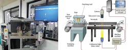
To improve inspection throughput and eliminate inconsistency, vision systems can be deployed to fully automate the terminal inspection process. Hence, when one terminal manufacturer in India required a vision system to make measurements of critical dimensions of its wide range of terminal pins, it called upon the expertise of National Instruments' (NI; Austin, TX, USA; www.ni.com) Alliance Partner Zentron Labs (Bangalore, India; http://zentronlabs.com) to develop a flexible vision-based cell specifically for the purpose (Figure 1).
The precision presses at the manufacturer's facility produce stamped and formed terminals at the rate of 1,200 parts per minute. Hence, the machine vision inspection was required to operate at the same rate. Compounding the inspection issue was the need to be able to set up the vision inspection system quickly to accommodate the numerous types of terminals produced by the manufacturer.
During production, it was important to ensure that the required dimensions of the stamped terminals were maintained. The tolerance to variations is small, so the accuracy and precision of the measurements made by the system was critical. More specifically, the terminal width needed to be measured at several places to an accuracy of +/-12μm with a precision of +/-3μm. It was also imperative to continuously monitor and record the statistical data to help measure the process and yield.
System development
In order to ensure that the vision inspection station could be moved between any one of many terminal production stations in the manufacturing environment, the system is not fixed to either the stamping machine or the winding machine, but is an independent standalone unit positioned between the two. During a production run, strips of formed terminals are fed through the vision station from the stamping press where they are inspected before being wound back on to the winding machine.
The vision inspection cell employs an embedded quad-core PC together with a dedicated PCI 6518 digital I/O card from NI to control the motion of both the stamping machine and the winder, ensuring that each terminal on a reel is sequentially presented to the cameras in the system. Once the images have been captured, NI Vision for LabVIEW software processes the images using a variety of image processing algorithms. Tools and functions within the LabVIEW software also enable the results of the image analysis to be presented to an operator on a HMI and the data logged into a database for quality control purposes.
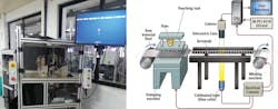
Due to the variety of terminal shapes and sizes, the types of inspection that need to be performed on each terminal type vary considerably. Hence the vision inspection system was designed in a modular fashion to accommodate one, two or three monochrome CCD cameras from Point Grey (Richmond, BC, Canada; www.ptgrey.com) all fitted with telecentric lenses from VS Technologies (Tokyo, Japan; www.vst.co.jp) to provide a constant magnification regardless of the specific location of the terminal in the field of view of the cameras. The three cameras enable three different aspects of the terminal to be captured, depending upon the nature of the inspection process that the manufacturer needs to perform on the terminal (Figure 2).
Every vision system is prone to nonlinear distortion errors, so the camera and lenses were calibrated for perspective and radial distortion using NI calibration algorithms to reduce the optical errors in the system and to enable translation to real-world coordinates from pixel coordinates. Using LabVIEW, utilities were developed to enable the cameras to be physically positioned and aligned in a precise manner.
Alignment of camera and lighting is critical as it requires the collimated light source to be perfectly aligned. In-house utilities developed in LabVIEW ensured that the alignment resulted in uniform distribution of light. Further, the utility also helped identify the exact focal plane such that it was at the center of the depth of field range. This rigorous exercise ensured that the accuracy provided by using these specialized optics components was effectively harnessed.
Terminal location and types
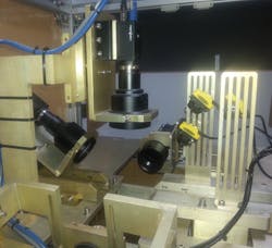
Because of the variety of terminal sizes, it was important to ensure that they could all be positioned within the field of view of the cameras in the system. To ensure that each type of terminal is guided into the correct position, an electro-mechanical assembly was developed which comprises a pair of grooved linear mechanical guides mounted onto a mechanical lead screw driven by a stepper motor.
Once a specific type of terminal is selected by the operator from the HMI running on the PC, the PC instructs the PCI 6518 digital I/O card to drive the stepper motor, which opens the guides attached to the lead screw to a predetermined coarse spacing (Figure 3). An operator can then manually insert a strip of terminals from the press through the guides on the machine and onto the winder. Before the vision inspection process commences, however, a second fine tuning operation is performed in which the guides are automatically moved closer to ensure that the terminal strips fit securely between them.

As a strip of terminals move through the system, a QS186LE photoelectric cell from Banner Engineering (Minneapolis, MN, USA; www.bannerengineering.com) is triggered to indicate the presence of a single terminal in the field of view of the cameras. The sensor triggers the three cameras which then capture images of the terminals from three different angles enabling not only the plane geometry, but also the solid geometry of the parts to be inspected.
During the process, the terminals are lit by a collimated backlight which directs light from an LED onto the terminal strips, producing a silhouette with highly contrasting edges, increasing the accuracy of the system by reducing diffuse reflections from the object. This makes the dimension captured objective and free from human errors that arise due to focus being set on either top or bottom surface of the connector.
The first of the three cameras - a Point Grey Grasshopper3 5MPixel GS3-U3-50S5M-C USB 3.0 camera - is mounted vertically, enabling a plane view of the terminals to be captured. The second - a Point Grey 4MPixel GS3-U3-41S4M-C USB 3.0 camera - is positioned at a 38o angle to the horizontal, enabling it to capture an image of two plane surfaces of the terminal, which allows the system to calculate more complex dimensions such as the thickness of the terminal at specific points along its length. A third horizontally mounted 4MPixel Point Grey Grasshopper3 GS3-U3-41S4M-C USB 3.0 camera points directly at the tip of the terminals, allowing any specific terminal features such as lip height to be measured.
Software analysis
The inspection software was developed using NI Vision for LabVIEW software. The Vision for LabVIEW software is organized into functional groups that enable images to be captured, manipulated and displayed, processed and then analyzed by the system.
Prior to deployment, the system is trained to identify and measure the key features of a terminal. To do so, the Vision for LabVIEW software is used to capture and create an image reference from which several regions of interest are identified, limiting the areas in the images in which image processing is performed. Once images are acquired by the three cameras during the inspection process, various edge detection algorithms in the NI Vision for LabVIEW software like IMAQ Rake 3, IMAQ Edge Tool 3 and Advanced Straight Edge Detection are used to detect straight edges in the images, while tools such as IMAQ Find Circular Edge 3 are used to find circular edges. Having found the edges of key features in the terminal, the software then measures the distance between edges, and edges and points, with sub-pixel accuracy.
The results from the image measurements are then compared against the acceptance criteria specified by the customer and presented to an operator on the HMI. If the inspection falls within acceptable tolerances, the stamping and winding machines are indexed to present a new part to the system. If the embedded PC detects a part that is out of tolerance, the PC instructs the PCI-6518 I/O card to halt the motion of the stamping and reeling machines. An operator can then highlight the location of the part on the roll before restarting the system.
Thanks to the use of NI hardware and software, the development of the vision inspection system was completed in four months. Using the new system, the terminal manufacturer is now shipping millions of terminals each year that have all been inspected thoroughly for dimensional accuracy. Since the machine was installed, it has inspected over 50 different types of terminal strips and made more than 250 different measurements on them.
In the future, Zentron Labs intends to enhance the vision inspection system to improve the throughput. To do so, it is evaluating marking every defective part that is detected, either by applying a visible ink mark to the terminal or by inflicting a dent of a specific shape on it to prevent the terminal from passing though any further plating or assembly processes. By doing so, the defective part can be removed from the reel at a later date, while inspection continues uninterrupted.
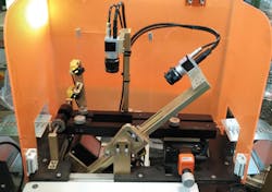
In a two-camera version of the existing system, Zentron Labs has deployed acA1600-20um cameras from Basler (Ahrensburg, Germany, www.baslerweb.com) fitted with VS-LD25N entocentric lenses from VS Technologies to create a cost sensitive variant that can be used in applications where manufacturing tolerances are relatively higher (Figure 4). In these applications, the largest measurement is in the order of 40mm with a tolerance of ±0.05mm, and the smallest is in the order of 0.28mm with a tolerance of ±0.05mm.
Krishnan Ramabadran, CEO, Zentron Labs, Bangalore, India (http://zentronlabs.com)
Companies mentioned
Banner Engineering
Minneapolis, MN, USA
www.bannerengineering.com
Basler
Ahrensburg, Germany
www.baslerweb.com
National Instruments
Austin, TX, USA
www.ni.com
Point Grey
Richmond, BC, Canada
www.ptgrey.com
VS Technologies
Tokyo, Japan
www.vst.co.jp
Zentron Labs
Bangalore, India
http://zentronlabs.com