High-speed vision system targets ballistics analysis

Coupling a high-speed camera and illumination system allows researchers to study the motion of projectiles in flight.
Dr. Chris Yates
Attempting to capture high-quality images of extremely fast events is a challenging task, but yet is required by many analysis applications. From the identification of critical material failure modes, through to analyzing the dynamics of MEMS, to the capture of ballistic projectiles, two opposing system requirements must be met. On one hand, extremely fast exposure times are needed to 'freeze' an instant of time without polluting the resultant image with unwanted motion artefacts. At the same time, sufficient light must be captured by the camera to create a high contrast image.
Traditionally, this balance has been achieved by illuminating scenes with high brightness flood illumination and using high speed image capture systems, often with large, sensitive pixels. In this approach, short exposure times are provided by the image sensor and the stream of images are stored to memory located on board the camera. These types of systems perform extremely well and often produce captivating image sequences, but at the same time represent a significant up-front investment and require additional external lighting.
Bullets in flight
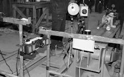
Tasked with capturing such high-speed images for a ballistics application, odos imaging (Edinburgh, Scotland; www.odos-imaging.com) has developed a coupled camera and illumination system. To perform the task, the company's SE-1000 high-speed recording camera and IL-0900 illumination modules were deployed in an ordnance testing facility to capture of high resolution, static images of high-velocity rounds after they exit from a rifle muzzle (Figure 1).
The SE-1000 complemented a conventional high-speed video recording system also employed by the test facility that was used to provide an overview of the entire scene. However, while this system provided high frame rates and high resolution images, it could not capture detailed static images of the projectiles in flight. Such images are required for inspection of the rifling imparted on the projectile by the barrel of the gun, and provide a visual analysis of any unwanted pitch or yaw on projectile motion that increase drag and decrease precision.
The customer required images of bullets in flight to be captured a short distance from the muzzle with sufficient magnification to allow visual analysis of the projectile markings and flight characteristics. A falling counterweight was used by the test facility to initiate firing of the rifle, and inherent timing uncertainties in this mechanism meant that it was not possible to trigger the camera directly from the counterweight. Instead, it was necessary to trigger image acquisition directly from the traveling projectile.
In the ballistics testing system, triggering is performed by placing a foil trigger sheet directly in the path of the bullet (Figure 2). The trigger from this sheet is connected to the general purpose I/O connector of the SE-1000 camera, via a DG535 pulse generator from unit from Stanford Research Systems (Sunnyvale, CA, USA; www.thinksrs.com). When a bullet passes through the foil, a transient electrical signal is generated and used to initiate image capture. The SE-1000 camera has the advantage of a low latency and jitter trigger input. With input latency of less than 1 microsecond, equivalent to the bullet traveling less than 1mm across the field of view, the time between trigger and exposure is short enough to guarantee that the bullet will not yet have entered the field of view of the camera.
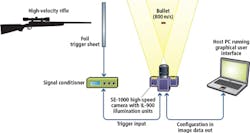
IL-0900 infrared illumination modules, emitting at 905nm, are arranged to illuminate the field of view and provide sufficient light intensity to obtain high contrast images. These illumination units trigger directly from the camera head, with a configurable delay from the input trigger to ensure even high speed rounds are captured at a moment in time.
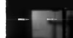
The relatively short trajectory length of a bullet within the 30cm field of view of the camera's APO-XENOPLAN 2.0/20 lens from Schneider-Kreuznach (Bad Kreuznach, Germany; www.schneiderkreuznach.com) equates to a transit time of just 400μs. The focal length of the lens was 20.5 mm and the camera was placed approximately 35 cm from the path of the bullet. To capture images without motion blur, the coupled IL-0900 illumination modules output 200ns light pulses that equate to the bullet traveling less than 0.2mm, eliminating any possibility of motion blur (Figure 3). The high intensity of the light pulse ensures the image is well lit and will result in a high-contrast image capture.
To allow analysis of dynamic motion of the projectile to be performed, a 'multi-pulse' illumination scheme can be used. In this mode of operation, the image sensor shutter is opened when the trigger detected. Multiple illumination pulses are sequenced, with a different delay pre-set in time, but timed to start after the projectile arrives and before it leaves the field of view. As each illumination pulse is captured within the same image frame, a composite image is formed. Delays between illumination pulses are calculated based on anticipated muzzle velocity of the bullet, and multiple images of the bullet in motion are captured.
The delay between each pulse is precise, allowing for detailed analysis of the captured images: most significantly projectile velocity and rate of rotation. With three or more images of the same bullet, it is also possible to extract data about the deceleration of the bullet due to drag or air resistance (Figure 4). Drag parameters and the modeling of drag on various projectiles are of critical interest within the ballistics community, particularly for projectiles fired at supersonic speeds.

Multiple exposures
Images are captured using odos imaging's todim::streamer GUI software, which is provided as open source software with each camera. All configuration and data transfer between the camera and host PC is achieved with a standard GigE Vision interface, together with a GenICam compliant API and images are stored as raw binary 16-bit files.
In Figure 4, three individual exposures of the bullet can be seen. Each pulse allows a well-exposed image of the bullet in flight. The presence of a BP-880 band-pass filter from Midwest Optical Systems (Palatine, IL, USA; www.midopt.com) minimizes influence of background light during the total exposure time of 500μs. With this filter in place, the infrared optical pulses provided by the IL-0900 modules are much greater than the background light and effectively illuminate and "freeze" the motion of the bullet.
In this test, the projectile was measured at 751m/s (compared with the manufacturer's supplied data of 854m/s) although the system has capability to reduce the optical pulse width down to 10ns, allowing imaging of projectiles up to twenty times faster.
Freezing time
To measure the exit velocity of the bullet, the delay between optical pulses was set to 100 microseconds, or approximately 8cm for a bullet traveling at 800 m/s. This delay was chosen to isolate the multiple exposures of the bullet within the composite image. The length of a bullet was known from the manufacturer's specification and used to provide an accurate scale to the images. Then the distance between the three visible exposures of the bullet could be precisely extracted.
A key advantage to the multi-pulse approach is the lack of influence of any frame-to-frame variability. Each exposure of the bullet is captured within a single activation of the camera sensor, and with well-controlled illumination timings, the number of sources of variability is minimized allowing improved analysis and increased accuracy. This can be seen in the analysis of deceleration of the bullet. Two instantaneous measurements of velocity are sufficiently precise to provide an accurate measurement of deceleration. One unique output from this capture sequence is the visible 'wobble' or 'yaw of the bullet, which is visible in the multiple exposed image. This type of motion is difficult to predict and provides invaluable input for ballistics manufactures.
In the ballistics imaging system, control of all three critical elements of the imaging process - trigger, illumination, and image capture - is performed within a single software interface.
While the SE-1000 and IL-0900 systems do not duplicate the complete functionality of traditional dedicated ultra-high-speed video recording cameras, the combination of on-board triggering and sequencing, high-speed image acquisition and matching high-power illumination sources suggests such systems will find use in range of test and analysis applications.
Dr. Chris Yates,
Chief Executive Officer,
odos imaging
(Edinburgh, Scotland; www.odos-imaging.com)
Companies mentioned
odos imaging
Edinburgh, Scotland
www.odos-imaging.com
Schneider-Kreuznach
Bad Kreuznach, Germany
www.schneiderkreuznach.com
Stanford Research Systems
Sunnyvale, CA, USA
www.thinksrs.com
Midwest Optical Systems
Palatine, IL, USA
www.midopt.com