3D Imaging: Fringe projection provides fast 3D surface analysis
Numerous techniques now exist to capture 3D images of objects. These include passive systems such as stereo camera implementations that only require ambient lighting and active systems that employ structured laser light or projected pattern-based lighting. While each technique has its own advantages and disadvantages and price/performance tradeoffs, the use of fringe projection techniques is especially useful in inspecting large specular objects such as automobile panels.
Today, a number of companies produce systems that use fringe projection techniques to capture and analyze images of 3D objects. Typically, these systems are composed of a projector that projects a sinusoidal fringe pattern onto the object and at least one camera that is used to capture the reflected fringe pattern that has been phase modulated by the object being measured. Captured images are then analyzed to produce a continuous phase distribution which is proportional to height variations of the object.
To project fringe patterns onto the object, companies such as 3D Dynamics (Gravenwezel, Belgium; www.3ddynamics.eu), GFMesstechnik (Berlin, Germany; www.gfmesstechnik.com) and ShapeDrive (Munich, Germany; www.shape-drive.com) use digital light projectors (DLPs) from Texas Instruments (TI; Dallas, TX, USA; www.ti.com) while Stefan Werling and his colleagues at the Fraunhofer Institute of Optronics (www.iosb.fraunhofer.de) have used a 42-in. diagonal LCD diffuse display as a pattern generator to illuminate the object to be measured (see "Phase measurement technique detects defects in specular surfaces," Vision Systems Design, February 2013; http://bit.ly/1yIyHgY).
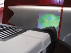
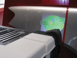
One of the limitations of these systems is that the 3D image generated by such systems is displayed on a computer monitor interfaced to the fringe projection system. "If operators need to mark or repair problem areas on the object, they must then look - or walk - back and forth between the monitor and the target object, a task that is both time consuming and prone to error," says Erik Klaas, Co-founder and CTO of 8tree (Denver, CO, USA; www.8-tree.com). To overcome this problem, 8tree has developed a patented implementation of 3D fringe projection technology that is embodied across its entire product portfolio. In each of its three products -fastCHECK, dentCHECK and gapCHECK - the system both projects fringe patterns onto the object, computes its 3D height variations and projects the results back onto the part.
In the design of the system, a DLP3000 DLP is used to project fringe patterns onto the part. Reflected images are then captured by an integrated GigE Manta G-031B camera from Allied Vision (Stadtroda, Germany; www.alliedvision.com) that features a 656 x 492 ICX618 EXview HAD CCD sensor from Sony (Park Ridge, NJ, USA; www.sony.com). An on-board i5 processor from Intel is then used to process the reflected images, extract measurement data from the detected distortions and derive a resultant image. The processor then warps this image to compensate for distortions from the projector and projects the resultant image on the measured surface, along with other optional information such as summaries, instrument status, menus and operator instructions. All this happens within one or maximum two seconds.
At last year's VISION show in Stuttgart, 8tree demonstrated how its dentCHECK product could be used to detect defects in a car body. Positioned 0.5m from the part, the scanner can resolve defects as small as 0.03mm in diameter across an 8.5 x 11in area. Projected data is then used to highlight the defect's dimensions and depth. The fastCHECK product has also been employed to inspect rivets in aircraft bodies where the system is used to instantly highlight non-conforming fasteners with color coded "go/no-go" feedback for the operator.

