High-speed camera systems measure vehicle dynamics
Automobile prototypes must be thoroughly evaluated so that final production models perform in an optimum manner. To do so, manufacturers must test their prototypes, evaluating how they perform at different speeds, road and handling conditions. In the past, such tests were performed by fitting numerous electro-mechanical and electro-optical sensors to each vehicle, capturing the data and comparing this with simulation models. While effective, such systems required multiple sensors to be precisely positioned on each vehicle, a task that is both time consuming and subject to generate inaccurate measurements.
To alleviate this problem, Aicon 3D Systems (Braunschweig, Germany; www.aicon3d.com) has developed a number of systems that use high-speed cameras to measure wheel and engine motion at vehicle speeds of up to 250kph.
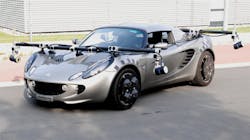
"Such tests provide information about the operating behavior of vehicles and feedback to development teams to validate their theories," says Theo Geluk, a test engineer at LMS International (Leuven, Belgium), now part of Siemens (Munich, Germany; www.siemens.com), a company that has used Aicon 3D Systems' WheelWatch to examine wheel movement in relation to the bodywork of the vehicle. To accomplish this task, a vehicle fitted with the WheelWatch system captures images of fiducials mounted on both the wheel and the fender of the vehicle (Figure 1).

"The custom fiducials mounted on each wheel are faceted and coded with an individual dot patterns so that the camera captures images of each fiducial as the wheels of the automobile are turned," explains Robert Godding, CTO of Aicon 3D Systems. Similarly, fiducial markers mounted on the fender are individually coded so that the results of positional information obtained from markers on the wheel can be correlated.Before the x, y, z, spin, camber and steer of the wheel can be determined, the pixel coordinates of each of dot patters on the wheel and fender are first located in 3D space. "At speeds up to 250kph and with up to 500fps," says Godding, "PC-based image processing cannot be used."
Instead, Aicon 3D Systems uses off-the-shelf FPGA-based 1.3MPixel high-speed CMOS cameras running at up to 500fps to accomplish this task. These cameras use image processing software embedded in the FPGA to locate the position of each of the dots on the fiducials of both the wheel and the fender. Raw data is then transferred over the cameras Gigabit Ethernet interface to a host computer, processed to provide information about the coordinates and position (6DOF) of the fender and the wheel in 3D space and stored for later analysis.
To ensure that these images can be captured under various lighting conditions, including bright sunlight, Aicon 3D Systems has embedded 300 LED lights into each of the cameras. These LEDs are then strobed simultaneously using the company's Sync hardware with the high-speed cameras to ensure that successful "stop-motion" image data is captured by each of the cameras.
After processing an ASCII file containing x, y, z, spin, camber and steer data is then provided to the user. This time-stamped data can then be compared with other synchronized data obtained from other sensors on the vehicle that may include the positional information of the car, speed, acceleration and the steering force applied. Using the system, a positional accuracy of approximately ± 0.1mm and an angle accuracy of approximately ± 0.015° can be obtained, according to Godding.
Major automobile manufacturers already use AICON's WheelWatch to measure wheel positions and compare the data from simulation models. Some of them formerly used optical systems based on active LED-markers or other techniques. These, however, are sensitive to sunlight and relatively heavy, which can influence driving behavior. The WheelWatch system is independent from the influence of light.
About the Author

Andy Wilson
Founding Editor
Founding editor of Vision Systems Design. Industry authority and author of thousands of technical articles on image processing, machine vision, and computer science.
B.Sc., Warwick University
Tel: 603-891-9115
Fax: 603-891-9297