May 2015 Snapshots: Smart cameras, imaging Comet Lovejoy, vision-guided robot
Smart camera system inspects automotive clips
Automatic Spring Products Corp. (ASPC; Grand Haven, MI, USA;www.automaticspring.com) manufactures stainless steel retainer clips, which are used in automotive fuel injection systems. "Manually inspecting the clips is both a time consuming and labor intensive process and does not provide quantifiable dimensions," says Beth Roberts at ASPC. "With our existing manual inspection process, we could only classify if each clip was good or bad. We had no way of knowing how accurate the dimensions of each clip were and exactly where each clip was within a 0.1mm tolerance. Most importantly, we weren't capturing statistical data that we could use to evaluate our process capabilities," she says.
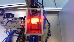
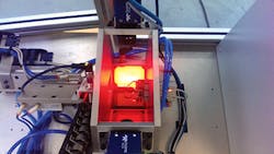
To automate the inspection process, ASPC contacted IP Automation Inc. (Addison, IL, USA;www.ipautomationinc.com to develop a vision-based inspection system. IP Automation Inc. and ASPC collaborated on the design of a system that comprises two BOA smart cameras from Teledyne DALSA (Waterloo, ON, Canada; www.teledynedalsa.com) with embedded iNspect imaging software. The BOA smart cameras used featured 640 x 480 monochrome CCD sensors with gauging tools and OCR and pattern recognition capabilities.
To inspect these clips, an operator first loads approximately 70 clips on a rail. As the clips move down the rail, they are grabbed by a gripper that places them on a platform in front of the two smart cameras. The first camera is placed to capture a side view of the clip, while the second camera captures an image of the clip from above. The vision system then assesses the dimensions of each clip and if the clip meets the pre-set requirements, it is saved. If it does not mean the specifications, it is discarded.
Dimensions of the parts are logged, and quality engineers can then analyze the data to determine the standard deviation of the measurement and compile quality logs for later use and to improve the manufacturing process. "From an operational standpoint, we have increased productivity rates and are seeing major labor and time savings. We can inspect about 30 clips per minute, a rate that was impossible when we checked each clips dimensions manually. The most time consuming part of the inspection process is the time required for the operator to load clips onto the rail that moves the clips into view of the cameras. We now also need only one operator rather than several inspectors, which is significant savings in manpower. However, the greatest benefit of the system from our perspective is that we're able to ensure the accuracy of the clips we deliver to our customer," says Roberts.
Vision system monitors patient-physician interactions
"Lab-in-a-box," as it has been dubbed by researchers from the University of California, San Diego's (UCSD; La Jolla, CA, USA;www.ucsd.edu) Computer Science and Engineering (CSE) department, is a vision and data collection system designed to analyze a physician's behavior and better understand the dynamics of the interactions of the doctor with the electronic medical records and the patients in front of them.
The project-which has an ultimate goal of providing useful input on how to run a medical practice more efficiently-was developed as a result of the fact that, quite often, physicians pay attention to information on a computer screen, rather than looking directly at the patient, according to UCSD.
"With the heavy demand that current medical records put on the physician, doctors look at the screen instead of looking at their patients," said Nadir Weibel, a research scientist at UCSD. "Important clues such as facial expression and direct eye-contact between patient and physician are therefore lost."
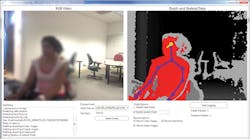
Lab-in-a-box consists of a set of sensors and tools that will record activity in the office. A Kinect depth camera from Microsoft (Redmond, WA, USA;www.microsoft.com) is used to record body and head movements, while an eye tracker from SensoMotoric Instruments (Teltow, Germany; www.smivision.com) follows where the physician is looking. Images from this tracker are transferred to a PC-based frame grabber from Epiphan (Ottawa, ON, Canada; www.epiphan.com). In addition, a microphone is used to record audio and the system also interfaces with the physician's workstation, where it monitors keyboard strokes, mouse movement, and pop-up menus that may distract the doctor.
Perhaps most importantly however, is the accompanying software that is designed to merge, synchronize, and segment data streams from the various sensors, to provide insight on which activities may led to distractions for the physician. For example, a great deal of head and eye movement may suggest that the doctor is multitasking between the computer and the patient, according to Weibel.
The Lab-in-a-box team will compare data from different settings and different types of medical practices to identify distraction-causing factors. Their findings may also help software developers write less-disruptive medical software. Furthermore, the team envisions deploying the toolkit permanently into physicians' offices to provide real-time prompts to warn that the doctor may not be paying enough attention to a patient.
The Lab-in-a-Box has been developed as part of Quantifying Electronic Medical Record Usability to Improve Clinical Workflow (QUICK), a running study funded by the Agency for Healthcare Research and Quality (AHRQ) and directed by Zia Agha, MD. The system is currently being used at the UCSD Medical Center and the San Diego Veterans Affairs Medical Center.
CCD camera captures image of Comet Lovejoy
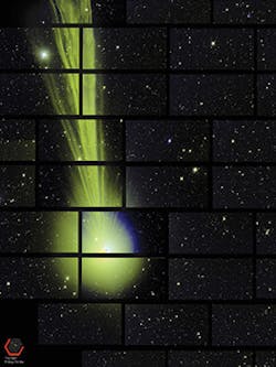
Developed at the US Department of Energy's Fermi National Accelerator Laboratory (Batavia, IL, USA;www.fnal.gov), the Dark Energy camera has captured an image of Comet Lovejoy while recently photographing the southern sky to study the nature of dark energy.
Each of the panels in the image (shown full-size athttp://bit.ly/1HXLa4u) was captured by one of the camera's 62 separate CCD image sensors, during an exposure on December 27, 2014. Each of the 62 CCD sensors has a 2048 x 4096 pixel focal plane array. The quantum efficiency of the CCDs-which were designed at Lawrence Berkeley National Laboratory (LNBL; Berkeley, CA, USA; www.lbl.gov)-with their anti-reflective coating, is optimized to be > 90% at 900nm and over 60% over the range of 400-1000nm. The camera operates at -148°F to minimize noise and dark current requirements with the cooling provided by liquid nitrogen. The Dark Energy Survey CCDs were fabricated by Teledyne DALSA (Waterloo, ON, Canada; www.teledynedalsa.com), with further processing performed by the LBNL.
The image of Comet Lovejoy was captured while traveling 51 million miles from Earth. Researcher Brian Nord says that the image of the comet was actually a mistake. "This was an accidental catch, because the Dark Energy Camera scans the sky over a very large region. The camera happened to scanning that part of the sky at the time."
Vision-guided robot helps cleanup oil spill
Researchers at William and Mary's Virginia Institute of Marine Science (VIMS; Gloucester Point, VA, USA;www.vims.edu) have developed a vision-guided remotely operated vehicle (ROV) that uses sound waves to locate and gauge the thickness of oil slicks caused by a spill.
A major challenge that cleanup crews face during an offshore oil spill is determining how much oil is involved, says Paul Panetta, VIMS adjunct professor and scientist with Applied Research Associates (Albuquerque, NM; USA;www.ara.com). "Gauging the volume of a spill, and the extent and thickness of its surface slick, are usually performed by visual surveillance from planes and boats, but that can be difficult," said Panetta, "our ROV uses acoustic signals to locate the thickest part of the slick."
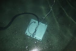
The ROV is built around waterproof motorized tracks that are rated to a depth of 100ft, have a top speed of 32ft/min, and can pull up to 100 lbs. On top of the tracks is an aluminum platform that houses the vehicles sensors, which include four acoustic transducers to send and receive sound waves and two video cameras that enable the operator to steer the robot. The robot's main electronics are in a plastic case above the waterline. The ROV is tethered to these electronics by 130ft cables. A computer connects to the electronics via Wi-Fi, so that the operator can operate the ROV from the surface.
Thickness of the oil spill is determined by sound waves emitted from the ocean floor. These waves reflect off the water and oil, oil and air, or oil and ice. Measuring the delay between the reflected echoes allows the vehicle to gauge the thickness of surface and below-ice oil slicks less than 0.5 mm thick to more substantial accumulations of up to several centimeters. This is an important since knowing the spill volume is key in mounting an effective response, including decisions about applying the correct amount of chemical dispersant.
Panetta's robot was prototyped at the 2.6M gallon Ohmsett Wave Tank in Leonardo, NJ, USA, and will now be used by Ohmsett staff and other research teams. The goal of the project is to refine the technology where it can help respond to spills in the open ocean. "We have already thought of several improvements," said Panetta, "such as creating a database of the acoustic properties of different types of oil as a function of temperature."
