Imaging system balances crankshafts
Olivier Bommart
Automotive crankshafts convert the reciprocating motion created by an engine's pistons into a rotational motion. To do so, they employ crankpins, bearing surfaces whose axes are offset from that of the shaft of the crank, to which the big ends of the connecting rods from each of the cylinders in the engine attach.
Crankshafts can be quite complex in their shape and function. They are usually manufactured from forgings, castings or billets of steel. Owing to manufacturing variations, manufacturers must determine whether a crankshaft is balanced before it can be assembled into an engine. The balancing process reduces internal loads and vibrations that would be harmful to the life of the engine.
To balance a crankshaft, it is mounted on fixtures known as stanchions in a dedicated balancing machine and then progressively spun throughout its full operating speed. By measuring the displacement of sensors attached to the stanchions while the crankshaft is spinning, the balancing machine can determine the location of any excess material along the axis of the crankshaft that is causing the imbalance.
Having done so, the counterweights on the crankshaft - which counteract the centrifugal force created by each individual crankpin - can be machined to remove weight by drilling or milling. The crankshaft is then rebalanced on the machine to determine whether the machining operations have been effective or if more machining (and further rebalancing) is required.
Balancing with vision
Traditional crankshaft balancing systems are far from ideal. The production process may involve several machining steps to ensure that a crankshaft is truly balanced satisfactorily. And the long and tedious number of machining operations that are involved may result in a part that is still not perfectly balanced and may need to be scrapped.
Now, however, a system has been developed by Videometric (Les Martres De Veyre, France;www.videometric.com) that promises to make the mechanical measurements taken by traditional crankshaft balancing machines a thing of the past, while overcoming all of their shortcomings. Although the vision-based system is currently only a prototype, it has already successfully passed several industrial tests that could qualify it as ready for use in an on-line production process.
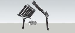
The prototype system comprises two sets of eight carbon-fiber stereo-heads placed apart from one another at a 120° angle which point directly down onto the surface of a production crankshaft. Each of the arms holds a ML500 video projector from Optoma (Fremont, CA, USA;www.optoma.com) based on a 1280x800 Digital Light Processor (DLP) from Texas Instruments (TI; Dallas, TX, USA; www.ti.com) and a pair of TXG03 640x480 GigE PoE monochrome cameras from Baumer (Frauenfeld, Switzerland; www.baumer.com) equipped with standard "industrial grade" C-mount DF6HA-1B 6 mm lenses from Fujinon (Tokyo, Japan; www.fujifilm.com) mounted at the end of each of the arms (Figure 1).
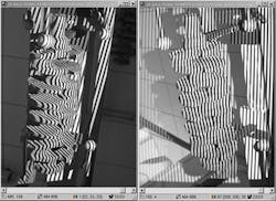
Once a crankshaft has been placed inside the housing of the system, a PC triggers each video projector sequentially, which then project a set of alternating sinusoidal fringe patterns of monochrome non-coherent light with spatially varying intensity onto the surface of the crankshaft at 60fps. As the patterns of light are projected onto the crankshaft, the geometric shape of the crankshaft surface distorts the projected structured-light patterns (Figure 2).
Each pair of Baumer monochrome cameras, which are synchronized to the video projectors, then captures images of the geometrically distorted fringe patterns scattered from the surface of the crankshaft at 60fps. The whole scanning process is performed three times, during which time the crankshaft is rotated through 120° between each digitization phase to enable an entire 3D model of the crankshaft to be captured.
Processing the images
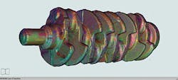
The 300kByte monochrome images of the distorted grey-scale fringe patterns captured by the pairs of cameras are transferred over Gigabit interfaces to a Gigabit switch that distributes the images to a second PC where each set of images from the cameras are processed. Here, proprietary Videometric system software measures the geometrical distortion of the patterns from each of the cameras as they are received, ultimately producing a very dense 3D point cloud of over 1.4 million of points in less than 0.9s for each stereo head (Figure 3).
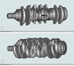
The 3D point cloud - which represents a set of coordinate points on the surface of the crankshaft in 3D space that represent its external surface - is then processed further to reconstruct a meshed closed surface, or 3D model which perfectly represents the crankshaft at an accuracy of 0.01mm in all three axes. The resultant image is then displayed to the user on a third PC where further analyses can be performed (Figure 4).
Having digitized the entire crankshaft and created an accurate 3D model, the Videometric software can compare its raw 3D shape to a CAD/CAM model of the original crankshaft design that is stored in the manufacturer's database. In doing so, the system can determine how well the production part conforms to the solid model and its dimensional tolerances.
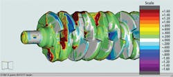
The software calculates the distribution of mass along the length of the crankshaft. The mass of the crankshaft - and how that mass is distributed along its length - both affect the mass moment of inertia of the crankshaft about its axis of rotation. Hence by calculating the mass moment of inertia of the original CAD model and comparing it to the mass moment of inertia calculated from the digitized 3D image of the production crankshaft, it is possible for the system to display any discrepancies between the original CAD model and the production part (Figure 5).
Having highlighted where any possible overweight areas are located on the crankshaft, the software can determine the amount of tooling required to machine the production crankshaft, or whether the part is impossible to tool further and should be scrapped.
If the crankshaft can be tooled, the software can simulate the tooling operations and determine the optimum tooling path that would need to be taken by a machine tool to correctly machine the virtual model of the production crankshaft, and what the new axis of inertia and weight distribution of the crankshaft would be after just one machining process. The tooling path could then be output to a machine tool to enable it to optimally machine the part such that it would be finally balanced.
Speed and accuracy
Currently, the company has shown that the prototype system is capable of achieving the speeds and the accuracy that would be required on a crankshaft production line. To qualify for use on a production line, a traditional electro-mechanical balancing machine must balance a crankshaft in less than 45s (the current industrial standard). The Videometric system, on the other hand, is capable of performing the same operation in less than 32s. Similarly, tests of the Videometric demonstrator system have shown that it is also capable of determining the overweight of a crankshaft at an accuracy of machines in use today.
Having demonstrated the viability of the initial prototype model, Videometric now plans to build a demonstrator version of the system. This will comprise a tunnel into which a crankshaft can be automatically conveyed. The arms housing the cameras and the DLPs will be located circumferentially around the tunnel, enabling the system to capture a 3D image of the part faster than the prototype, since there will be no need to rotate the part three times during the image acquisition process. Current estimates are that the system could reduce the time taken to virtually balance a crankshaft down to between 20-25s at an accuracy of 1 micron.
At present, the Videometric vision-based prototype has been evaluated by a number of major crankshaft balancing system manufacturers that have expressed an interest in the system. Once Videometric has built its demonstrator system, it may choose to sell the patent rights to such system builders, or to license the design of the system to a number of them.
Olivier Bommart, Videometric, Les Martres De Veyre, France
Companies mentioned
Baumer
Frauenfeld, Switzerland
www.baumer.com
Fujinon
Tokyo, Japan
www.fujifilm.com
Optoma
Fremont, CA, USA
www.optoma.com
Texas Instruments
Dallas, TX, USA
www.ti.com
Videometric
Les Martres De Veyre, France
www.videometric.com

