Vision helps inspectors check aero engine blades
Robert Fisher
Many contemporary vision systems deployed in industrial production lines capture images of products so that that they can be automatically inspected by image processing software, after which they are either accepted or rejected. However, when a large UK-based manufacturer of aero engines required a system to assist with the inspection of the main fan blades which are used on its jet engines, the requirement was somewhat different.
Instead of automatically processing images of the blades, the manufacturer simply wanted to capture their images so that inspectors could manually determine and document the nature of any potential faults. In this way, the system could replace the previous method of inspecting the blades by human operators using micro-binoculars.
In doing so, the manufacturer could meet the regulatory requirements that specify that the fan blades must be inspected manually, while enabling greater traceability and repeatability in its production processes around the world.
To reduce the weight of fans used in aero engines, modern aircraft blades are hollow. The hollow blades are formed from three sheets of titanium which are bonded together. Each blade sports two outer sheets and one inner sheet - a thin membrane which forms a honeycomb structure within the body of the blade.
The shape of the turbine blade is complex - it consists of a 'root' at the base of the blade, an aerofoil surface and a 'shroud' at the top. The root of each blade is attached to a fan disc. A single disc with approximately one hundred blades attached to this forms a 'stage', of which there are several in each section of the engine.
Due to the nature of the production process, the root of the blade must be rigorously inspected to determine if its quality is acceptable. By inspecting the membrane bond line in the curved root of the blade, it is possible to determine whether the sheets of titanium have been bonded together effectively along its length and whether there is any porosity in the membrane itself.
Vision inspection
To create a system to enable it to carry out such inspections on blades of a variety of different sizes, the aero engine fan blade manufacturer called upon the expertise of UK-based Fisher Smith (Ringstead, Northamptonshire, UK; www.fishersmith.co.uk) that developed a custom PC-based vision system specifically for the task.

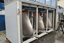
Prior to inspection, the heavy blade itself must first be mounted with its root facing upwards into one of a number of fixtures which can accommodate blades of different sizes and shapes (Figure 1). The PC-based vision system then captures images of the curved membrane at the root of the blade using a 2048 pixel-wide Runner monochrome line scan camera from Basler (Ahrensburg, Germany; www.baslerweb.com) fitted with a T45/2.0L telecentric lens from Vision and Control (Suhl, Germany; www.vision-control.com) which is mounted above the enclosure housing the blade. The telecentric lens ensures that the image magnification is independent of the distance of the root of the blade or its position in the field of view, enabling the camera to capture a 10mm wide image of the membrane at a resolution 0.005mm (Figure 2).

During the image acquisition process, a pair of Vision and Control LAL7-50/R-Ex red LED bar lights mounted on either side of the camera enclosure at a 10° angle illuminate a 10 mm strip in the middle of the root of the blade (Figure 3). As the camera traverses the curved length of the blade, the images of the membrane of the blade are streamed to the PC-based system over a GigE interface where they are stored for later analysis.

Capturing an accurate image of the membrane in the root of the blade was not a trivial process. Due to the nature of the blade manufacturing process, the root of the blade - and hence the membrane that runs through the center of it - is a complex shape. To complicate matters further, the precise distance from the root of the blade to the imager is initially an unknown quantity, since the roots of the blades are not machined prior to inspection.
Membrane tracking
To enable the line scan camera to traverse the blade in a preprogrammed path to accurately capture a linear, rather than curved, image of the membrane - and to compensate for any variations in height - it was imperative to move the camera in the x, y and z planes as well as rotate it. To do so, the PC is interfaced via Ethernet to a CompactLogix PLC from Allen Bradley/Rockwell Automation (Milwaukee, WI, USA; http://ab.rockwellautomation.com) which houses a four-axis motion controller.
To ensure that the vision system could accurately capture a linear image of the membrane, the shape of the curved root specific to each type of blade was first defined by a set of three interpolating curves. Once defined, the trajectory that the camera was to follow for each blade type was programmed into the Allen Bradley PLC system using RSLogix software. The software instructs the motion controller to actuate two electro-mechanical linear ball-screws that move the camera in the x and y plane. A rack and pinion actuator rotates the camera as it travels along the length of the membrane. In doing so, the imager in the line scan camera always remains at a constant 90° angle as it moves along the curved membrane.
Because the distance between the surface of the membrane and the camera lens is unknown, it was important to measure the distance during the image acquisition process and to adjust the distance between the lens and the surface dynamically. To do so, a Keyence (Osaka, Japan; www.keyence.com) IL-1000 amplifier and IL-030 laser displacement sensor mounted onto the camera enclosure measures the distance from the lens of the camera to the membrane of the blade. This data is then fed back to the PLC which uses the data to instruct the motion controller to actuate a further electro-mechanical linear ball-screw that moves the camera in the z axis. The result is that the distance of the camera housing to the root of the blade remains at a fixed working distance to within 0.1mm accuracy from the height of the blade.
To provide a degree of confidence that the machine has captured an image of the root of the blade accurately, the camera is scanned across a V-shaped calibration artifact before and after image acquisition. The two images captured by the camera are then transferred to the PC where they are compared in size and intensity using HALCON image processing software from MVTec Software (Munich, Germany; www.mvtec.com). Thus, the inspector can be assured that both the LEDs were operating during the acquisition process and that the uniformity of the light impinging on the membrane during the scan was consistent.
Inspecting the images
Once the membrane of the blade has been scanned by the vision system, the full set of acquired images are stitched together and displayed on the screen of the PC. At the bottom of the screen, a 'ribbon' image of the blade is displayed to the inspector, which shows the whole membrane bond line including images of the calibration object captured at the start and end of each scan (Figure 4).
During the inspection process, an inspector moves along the ribbon image, sequentially selecting sections of the membrane bond line to be magnified by the system. These magnified images are then displayed in a second window at the top of the screen. The inspector then scans each of the magnified images of the membrane for indications of any faults such as lack of bonding or porosity which can be identified as a single, or a series of bright areas on the image.
The blade inspection procedure is considered completed once the inspector has viewed all the magnified images of the membrane. Having identified any potential indication of faults, their location size and type is then marked on the image and their details stored in the system.
Once an inspector has completed an inspection, the system displays a screen that summarizes the potential indications of defects that he has found. Based upon the indications marked on the image, the system can then use a set of predefined criteria to determine whether the blade should be accepted or rejected. However, because it is a manual inspection process, inspectors are required to annotate this data with their own comments.
If a blade fails the inspection process, a laboratory technologist is called upon to view the image of the blade to provide a second opinion on the condition of the blade. He applies a second set of criteria to the inspection process and, having done so, also enters his own findings into the system.
In the past, the indications of faults and their location and type were marked on a paper document by the inspector. However, with the vision system in place, an electronic document can now be produced and stored that highlights on the image of the blade the number and type of indications of faults found within the membrane bond line. As such, the digital system enhances the ability of the manufacturer to trace the characteristics of the blade from the point of manufacture through to its subsequent deployment.
The present method of inspecting the roots of aero engine blades relies on the expertise of highly-skilled manual operators to perform the task. In future, however, a similar vision-based system may perform this task automatically. Such systems, however, would be subject to a highly stringent approval process due to the extreme safety concerns associated with the aerospace industry.
Robert Fisher, Partner, Fisher Smith LLP, Ringstead, Northamptonshire, UK
Companies mentioned
Allen Bradley
Milwaukee, WI, USA
http://ab.rockwellautomation.com
Basler
Ahrensburg, Germany
www.baslerweb.com
Fisher-Smith
Ringstead, Northamptonshire, UK
www.fishersmith.co.uk
Keyence
Osaka, Japan
www.keyence.com
MVTec Software
Munich, Germany
www.mvtec.com
Vision and Control
Suhl, Germany
www.vision-control.com