Applying terahertz technology to industrial automation

Systems based on terrahertz sources and detectors have become a candidate for industrial applications.
Trevor Dietrich
Traditional vision systems that employ visible light sources and detectors cannot be used to solve certain classes of industrial automation tasks. For example, visible light cannot pass optically opaque bottles such as shampoo bottles, nor analyze the material properties of black plastics to sort them for recycling. Traditional technologies also face other challenges, for example, when the inner and outer diameter of an enclosed part must be measured. While LED illumination and solid-state cameras can capture the outer diameter measurement, such techniques cannot determine the inner diameter.
These are some of the challenges solved by terahertz (THz) sensing. Because THz waves can readily pass through optically opaque materials such as cloth, paper, wood and plastic, the objects or defects behind them can be more easily visualized.
Terahertz technology
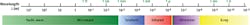
The terahertz region of the electromagnetic spectrum lies in the gap between microwaves and infrared (IR) and spans the wavelength range from 1mm-100µm, or frequencies from 300 GHz-3THz (Figure 1). Compared to x-ray energy, THz waves provide non-invasive and non-ionizing imaging due to their low photon energy.
Terahertz systems operate in either continuous-wave (CW) or pulsed wave (PW) mode. In CW systems, a semiconductor is excited with two IR beams with a frequency difference in the THz frequency range. In PW systems, the THz pulse is generated through exciting the semiconductor with a femtosecond optical pulse.
Depending on the application requirements, there are situations where each method is better suited. CW systems are generally more cost-effective, while PW systems can provide more detailed information for material characterization and depth information. In PW systems, material identification information is obtained over a range of frequencies (typically up to 5THz) while single frequency CW systems obtain information for a single frequency.
Terahertz systems can use single emitter and single point detectors to create a frequency profile of the object under test. These point detectors can be moved electro-mechanically to provide 2D and 3D scans. Alternatively, 2D linear line scan or 3D detector arrays can be used to generate 2D and 3D frequency profiles.
Terahertz in action
Thanks to the growth of telecom, semiconductor and laser markets and recent advances in semiconductor, laser and optical technologies, photonic-based terahertz sources and detectors have become a candidate for many industrial applications.
The identification of materials and features inside enclosures or behind barriers would traditionally be a difficult, if not impossible task. To accomplish such tasks, TeTechS (Waterloo, ON, Canada; www.tetechs.com) has developed its Vega terahertz in-line measurement system that can be used for non-destructive, non-invasive product inspection, hidden object and defect detection, thickness measurement, and density measurement.
Using a terahertz transmitter and receiver pair, the Vega terahertz CW system interacts with the sample at a single point and forms a frequency profile based on the absorption of terahertz radiation of the material under test.
Vega can also be extended to a line scan configuration where an array of sensor heads cover a 12in line that acquires a line of points simultaneously. The benefits of such a line scanner is that the acquisition time to create a terahertz line scan profile is considerably faster than employing a point scan system with a single point transmitter and detector that is mechanically moved across the field of view of the object.
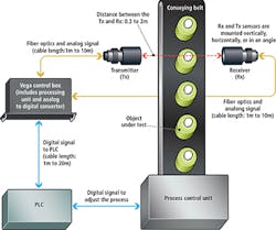
Figure 2 shows the Vega THz system integrated in a factory automation application. In this configuration TeTechS' T-Era antennas are used as both transmitter and receiver modules. A laser beam and a bias voltage power the modules. The laser beam is focused on the antenna through an optical fiber connected to the back side of the module. In this example, the object under test is moving on a conveyor belt and passes through the sensor's field of view. Captured THz waves are sent via an coaxial cable to the Vega control box. Here, an opto-mechanical delay system from THORLABS (Newton, NJ, USA; www.thorlabs) is used to capture and process the received high-frequency waveform. The resultant signal is then digitized and passed via Ethernet or other communication protocols to a standard PLC controller to initiate a pass/fail result.
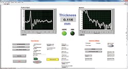
Vega's software is implemented using LabVIEW from National Instruments (Austin, TX, USA; www.ni.com). This controls the laser, the antennas, and the opto-mechanical linear translation stage and was used to generate the system's graphical user interface (Figure 3). While the left graph shows the time domain terahertz measured waveform (amplitude versus time), the right graph shows the calculated frequency spectrum of the measured waveform calculated using an FFT. While the time domain waveform can be used to characterize the thickness of a product under test, the frequency spectrum can be used to identify the type of polymer used in the product.
Terahertz applications
Often it is necessary to measure the wall thickness of opaque plastic or rubber bottles, hoses and tubes using non-invasive and non-destructive measurement techniques. Currently, to achieve a thickness measurement of opaque plastic bottles, two invasive and destructive methods are being used. The first method is to cut the bottles and measure the wall thickness using a caliper. This method is destructive and time consuming. Alternatively, the second method uses Hall effect probes but this is also time consuming and cannot be easily integrated into manufacturing lines. Vega provides a fast, no-contact, non-destructive precise measurement (~10um) technique for these thickness measurements.
In many plastic separation systems, the NIR portion of the electromagnetic spectrum is used to characterize plastic materials in waste streams by examining the spectral characteristics of the reflected light from the plastic flakes. However, NIR is only effective for light-colored plastics. If the plastic flake is black, dark, colored or painted, the NIR is absorbed and the NIR separation is ineffective. In the waste industry, the sorting of black plastic products is often achieved using Float Sink technology that uses the principle of density separation in water to separate products. This technique requires heavy water usage, water treatment, size reduction, final washing to remove salt residue and final drying of the recovered plastic stream. This process is much more energy intensive than optical separation systems. TeTechS' terahertz sensors overcome the limitations of both of these technologies and have successfully identified and classified different types of plastics including black plastics.
Leaky bags
In industrial inspection applications, the detection of leaky IV bags is currently performed using x-ray or light-based imaging. With certain materials, this method proves challenging due to the low contrast between the liquid and the plastic IV bag. In some cases, this challenge can be overcome with the use of a backlight. However, there are cases such as cloudy bags, where the backlight would not suffice and terahertz would be needed. Using the TeTechS Vega CW system, the presence of the liquid inside enclosures or IV bags can be verified and identified (Figure 4).
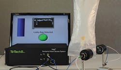
In this configuration, the THz transmitter and receiver modules are placed at about 20 cm away from the IV bags. The graph depicted is the amplitude of the detected terahertz signal by the receiver module. If no leaked liquid is present there is no noticeable drop in amplitude as the terahertz wave passes through the plastic bag. If liquid is present, as in this case, the amplitude of the reflected signal is lower indicating that the inner bag is leaking.
Trevor Dietrich,
Marketing Manager,
TeTechS Inc.,
Waterloo, ON, Canada (www.tetechs.com)
Companies mentioned
National Instruments
Austin, TX, USA
www.ni.com
TeTechS
Waterloo, ON, Canada
www.tetechs.com
THORLABS
Newton, NJ, USA
www.thorlabs.com