Smart vision system inspects bucket labels

A manufacturer of plastic containers has deployed a vision system to inspect the labels on circular buckets.
Brendan Forbes
Injection molding machines are often deployed in the manufacturing industry to fabricate open containers such as plastic buckets. After the buckets have been molded, they are typically conveyed into a labelling applicator which affixes pre-printed labels to their exterior surface. The buckets are then automatically inspected for defects, after which handles are attached to them. Lastly, the finished products are stacked and packed ready for shipment to a customer where they are filled prior to distribution.
The process of inspecting the labels on the buckets is a critical step in the manufacturing process. In today's automated manufacturing environment, such processes are commonly carried out by vision inspection systems. These systems verify that the correct labels have been applied to the buckets, ensuring that they have been positioned to within specified tolerances, and check them for defects, such as incorrectly printed labels or rips or tears.

When one Mid-Western bucket manufacturer based in Elk Grove, IL, USA, required a system to inspect the labels on a new range of cylindrical buckets, it called upon the expertise of machine builder Chicago Electric (Carol Stream, IL, USA; www.chicagoelectric.com) to develop a vision-based cell to automate the process.
In the past, Chicago Electric had designed a number of vision inspection systems for the packaging producer. However, those systems were built to check labels applied to the four sides of square or rectangular buckets. To do so, the buckets were rotated in an inspection station in four 90° increments in front of an area scan camera where they were momentarily held stationary while the camera consecutively captured and processed images of the label on all four sides.
To create a machine to inspect the cylindrical products, however, Chicago Electric took a different approach. The new imaging inspection station continuously rotates each cylindrical bucket while a line scan camera captures images of the label applied to the bucket line by line. The system then builds an image of the label, after which the curved surface of the label can be translated into a uniform 2D image that can be processed and analyzed for defects using off the shelf vision tools.
Automated inspection
In operation, molded buckets are transferred from the output conveyor of a labelling machine onto a custom-built split belt conveyor (Figure 1). This is driven by a VHI590S2T-GVR induction motor from Oriental Motor (Torrance, CA, USA, www.orientalmotor.com) powered by a drive from Emerson (St. Louis, MO, USA; www.emerson.com) under the control of a CompactLogix PLC from Allen Bradley (Milwaukee, WI, USA; www.rockwellautomation.com).
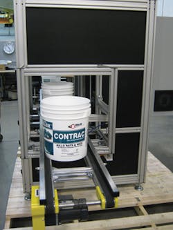
Unlike standard belt conveyors, the split belt conveyor does not employ a uniform carrying medium across its width. Instead, it has two belts with a cavity between them, enabling the buckets to be moved vertically in the inspection station by pneumatic actuators located beneath the conveyor.
One of the requirements demanded by the injection molding manufacturer was that the conveyor line should move continuously during the inspection process. To bring the bucket to a halt without stopping the conveyor, a LR-Z photoelectric cell from Keyence (Itasca, IL, USA; www.keyence.com) is triggered when the bucket enters the imaging station. The CompactLogix PLC then actuates two CDQ2A40 pneumatic cylinders from SMC (Noblesville, IN, USA; www.smcusa.com) which raise two pins in front of the path of the moving bucket to prevent any forward movement. A further set of pins is raised behind the bucket to prevent any buckets from entering the inspection station while the inspection process is taking place (Figure 2).
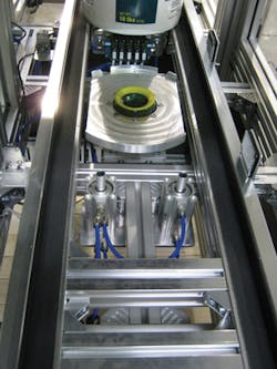
Once the bucket is stationary, the CompactLogix PLC triggers the SMC CDQ2A40 pneumatic actuator which lifts up a circular nest from beneath the conveyor, transporting the bucket from the conveyor and into the field of view of an In-Sight 5604 line scan camera from Cognex (Natick, MA, USA; www.cognex.com). As it does so, a vacuum is applied to a cylindrical aperture in the center of the nest to hold the bucket firmly in place.
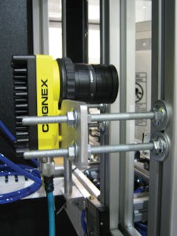
When the bucket has moved into the field of view of the camera, the PLC triggers the camera to enable it to start building the image of the label. The nest holding the bucket in position is then rotated by an Emerson NTM-207 motor driven by an Emerson Epsilon EP202 servo drive under control of the PLC. As the bucket is rotated, an encoder fitted to the drive triggers the camera to define when each line in the image should be captured. The In-Sight camera fitted with a Fujinon CF12.5HA-1 lens from Fujifilm (Tokyo, Japan; www.fujifilm.com) uses the trigger signals from the encoder to build the image based on the rotational speed of the bucket (Figure 3). To illuminate the label on the bucket, a UL-LL LED line light from Metaphase Technologies (Bristol, PA, USA; www.metaphase-tech.com) projects a thin strip of concentrated LED light onto its surface.
To ensure that a complete image of the label on the bucket is captured by the system, the bucket is rotated twice through 360o during the image acquisition process. Once the task is complete, the PLC instructs the drive to stop rotating the motor. Having done so, the bucket is lowered back onto the conveyor while the Cognex In-Sight software running on the line scan camera processes the images of the label.
Imaging tasks
The Cognex camera was programmed using Cognex's In-Sight spreadsheet interface. This enables job files to be created that contain formulas and text to perform three machine vision tasks. The first ensures that the correct barcode appears on the label, enabling the container producer to verify that the proper label had been applied to the bucket. To check the barcode, the Cognex In-Sight ID Max vision tool reads the barcode from the label, and its value is then transferred to the PLC over an Ethernet interface where it is matched to a value previously programmed into the system.
The second task performed by the vision system is to ensure that the label has been correctly affixed onto the bucket. To do so, Cognex's In-Sight InspectEdge tool determines the location of the top and bottom edges of the bucket and the top and bottom edges of the label. Having located all the edges, the In-Sight spreadsheet software calculates the distance of the label from the top and the bottom of the bucket. These values are then also transferred to the PLC where they are compared with predetermined settings to determine whether the position of the label falls within acceptable tolerances.
Lastly, the vision system performs a label quality inspection to determine if there are any unexpected tears, breaks or gaps in the label. Prior to doing so, the image of a known acceptable label was divided up into eight sections based on the known position of the barcode. Then, Cognex's PatMax geometric pattern matching tool was used to train the system to identify shapes in each of them and to create eight templates. By dividing the image into sections, the speed and the accuracy of the matching process is improved, enabling irregularities that are less than 1/8in in size to be identified.
In the production environment, matching is performed by finding the best similarity between the features extracted from the sections of images from the label on the bucket to the features found in the templates. The software then calculates a score for each match which correlates how closely the model matches the patterns captured by the camera. The scores are then transferred to the PLC where they are compared to the acceptable range of scores preprogrammed into the system. If there are any large tears or breaks in the label, then the correlation value will fall below a threshold and the bucket will be flagged for rejection.
After the full inspection sequence has been performed, and the PLC has determined whether the label on the bucket has met all the necessary inspection criteria, the bucket is lowered back onto the conveyor and the vacuum is released. The bucket is then carried down to a further section of the conveyor to a rejection station.
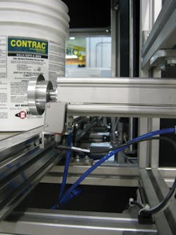
As the bucket enters the rejection station, a photoelectric sensor is triggered to determine its presence. If the bucket has passed the inspection, it continues down the conveyor. If it has failed, the PLC triggers an SMC CDQ2A40 pneumatic platform that lifts the bucket up vertically from the conveyor, after which an SMC CA2-Z linear pneumatic actuator pushes the bucket clear of the conveyor into a hamper (Figure 4).
User interface
The vision system is controlled and programmed through an HMI that was custom built using the SCADA/HMI EmbeddedView software package from InduSoft (Austin, TX, USA; www.indusoft.com) running on an industrial touchscreen PC from Pro-face (Ann Arbor, MI, USA; www.profaceamerica.com). Because the Cognex In-Sight software enables the InduSoft HMI software to directly access the functionality of the In-Sight spreadsheet running on the Cognex smart camera using OPC, it was possible to provide a great deal of functionality to the user interface.
As data can be seamlessly exchanged between the software running on the camera, the PLC and the HMI running on the PC, the inspection system can be taught to identify a new part in less than half a minute. To do so, an operator can instruct the Cognex's In-Sight software running on the camera to enter teach mode directly from the HMI.
To perform this task, a bucket with a known good label is loaded onto the conveyor and carried into the system. The vision software then identifies the new barcode and the location of the label on the bucket, and creates a new set of image templates for label identification which are stored as a new In-Sight job in the camera. The set of new values are then transferred to the PLC where they can be compared with those acquired during a production run.
The HMI also enables an operator to view the image captured by the camera on the HMI and, if necessary, to make changes to the threshold values that are deemed acceptable. Should the vision system detect any anomalies, such as incorrect barcodes, incorrectly positioned labels or defects on the label itself, the location of the anomaly is highlighted on the image and displayed on the HMI.
The interface also enables the operator to zoom in on any defects to examine the image of the label in more detail. The Pro-face industrial touchscreen PC is also capable of storing the images captured during the inspection process, enabling the packaging producer to track the type and number of rejected products and from that determine the root cause of any defects.
Brendan Forbes, Sales and Products Manager, Chicago Electric, Carol Stream, IL, USA
Companies mentioned
Chicago Electric
Carol Stream, IL, USA
www.chicagoelectric.com
Cognex
Natick, MA, USA
www.cognex.com
Emerson
St. Louis, MO, USA
www.emerson.com
Fujifilm
Tokyo, Japan
www.fujifilm.com
InduSoft
Austin, TX, USA
www.indusoft.com
Keyence
Itasca, IL, USA
www.keyence.com
Metaphase Technologies
Bristol, PA, USA
www.metaphase-tech.com
Oriental Motor
Torrance, CA, USA
www.orientalmotor.com
Pro-face
Ann Arbor, MI, USA
www.profaceamerica.com
Rockwell Automation/Allen Bradley
Milwaukee, WI, USA
www.rockwellautomation.com
SMC Corporation of America
Noblesville, IN, USA
www.smcusa.com