Vision checks optical characteristics of artificial corneas
A novel system quality checks and sorts specially packaged artificial corneas.
Gary Livingstone
Corneal blindness resulting from disease or physical injury affects thousands of people worldwide. In many cases, corneal transplants from donors can restore their vision. However, the shortage of suitable donor corneas has created the need to develop alternative treatments.
A common option is to replace a diseased cornea with an artificial cornea in a surgical procedure known as keratoprosthesis. In the procedure, the artificial corneas, which are made of clear plastic with excellent tissue tolerance and optical properties, are implanted into the eye by ophthalmologists, often on an outpatient basis.
One company actively involved in the development of such artificial corneas is Oxford MEStar (Oxford, UK; www.oxford-mestar.com), founded by Professor Zhanfeng Cui of the Institute of Biomedical Engineering of Oxford University.
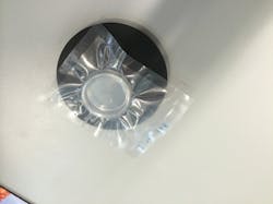
Although the specific nature of Oxford MEStar's cornea manufacturing process remains proprietary, once the artificial corneas have been produced, the corneas and their integral supporting scaffolds-which together measure about 35mm diameter-are suspended in a transparent gel after which they are packaged in a sealed clear plastic blister packs measuring 80 x 100mm. The blister packs are then vacuum-packed into a clear piece of packaging in a sterile environment (Figure 1).
Prior to shipment, each cornea must be inspected to ensure that its optical characteristics fall within stringent tolerances. To do so, Oxford MEStar initially employed a haze-gard plus laser analysis system from BYK Gardner (Geretsried, Germany; www.byk.com), which is widely used in the glass, plastic, film and packaging industries to measure the transparency of a product.
However, as effective as the system was at determining the transparency of the corneas, it still required a trained operator to place a package into the field of view of the system. After the laser light passed through the center of the cornea, the results were then analyzed.
Automated inspection
To simplify the process, Oxford MEStar wanted to semi-automate the inspection procedure to enable the corneas to be automatically accepted or rejected as part of an in-line production process. To do so, Oxford MEStar engineers called upon the expertise of LG Motion (Basingstoke, Hampshire, UK; www.lg-motion.co.uk) who worked with Scorpion Vision (Lymington, Hampshire, UK; www.scorpionvision.co.uk) to develop a vision-based motion control system specifically for the purpose.
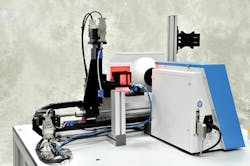
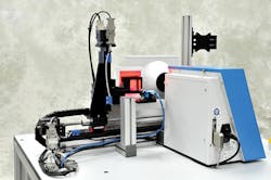
The system enables an operator to manually load a single package containing a cornea into a mechanical gripper after which it is conveyed to the vision station by a motion control system where the location of the cornea in the dish is determined by a dedicated Scorpion Vision Compact Vision System from Tordivel (Oslo, Norway; www.tordivel.no), see Figure 2. The motion control system then orients the package such that the centerline of the cornea is correctly positioned so that the laser light from the haze-gard plus system can perform an optical analysis.
The operation of the system is controlled by a dedicated single-board computer from Arduino (Somerville, MA, USA; www.arduino.cc) interfaced to an Arcus Technology (Livermore, CA, USA; www.arcus-technology.com) PMX-4 industrial stepper motor controller. The stepper motor controller regulates the motion of a pair of motorized linear slides that move the gripper holding the package vertically and horizontally, and actuates a drive which opens and closes the gripper, enabling the package to be loaded and unloaded.
The Arduino processor is also interfaced directly to the PC-based vision system and the embedded PC in the haze-gard plus system. If the vision system fails to identify the presence of a product in the package, or if the laser analysis system determines that a cornea does not meet the desired tolerances, the Arduino single-board computer then instructs the Arcus controller to move the part over to a chute where the grippers are released and the part rejected.
The mechanical motion system - which comprises custom stepper-driven ball screw positioning stages with single linear motion guide bearings-were designed specifically for the application. With a 500mm travel range for the horizontal axis and 50mm vertical travel, the stages include manual drive wheels to allow the operator to position the axes under power-off conditions to maintain the machine by checking the backlash, carriage rigidity, slide lubrication and adjusting the gripper mechanism.
Corneal inspection
In use, an operator must position the packaged cornea samples correctly to ensure the mechanical gripper holds them securely for processing. To do so, the operator places the bottom of the sample packaging in a groove on a loading platform and holds the sample upright until the gripper closes around the packaging (Figure 3).
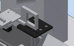
Once the inspection process is initiated by an operator from an HMI running on a touch screen, the grippers then slowly close, centralizing the package and holding it securely in place during the inspection procedures. Under control of the Arcus controller, the motorized linear stages then moves the package until it is aligned with the vision system.
Determining the location of the cornea with relation to the packaging proved a challenge. This was due to the fact that both the corneal scaffolds that contain the cornea - and the transparent gel that they are suspended in-are almost translucent. To resolve this issue, LG Motion worked with Scorpion Vision in the UK to develop a vision system to evaluate the appearance and location of the corneal scaffold.
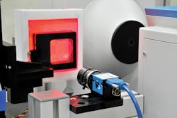
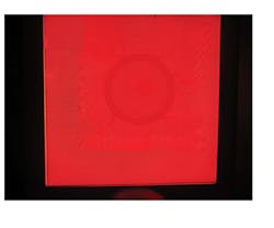
Once the package enters the vision station, the package containing the scaffold is illuminated by a red light LED light with a fine square weave wire mesh with a grid pattern of 0.25mm placed in front of it. Light projected through the mesh then impinges on the Petri dish and the cornea contained within it. The image of the grid pattern is then captured by a DMK 23UP031 USB3 industrial camera from The Imaging Source (Bremen, Germany; www.theimagingsource.com) and transferred over an interface to the Scorpion Vision Compact Vision System running Scorpion Vision software for analysis.
Since the grid pattern captured by the camera will be obfuscated by the edge of the Petri dish and the cornea, the image then reveals the location of the edge of the Petri dish and the cornea. The edge of the Petri dish can then be used to define a region of interest in which the cornea is likely to be found. Using the edge detection tools in the Scorpion Vision software, the circumference of the cornea can be detected. Next, using geometry tools, the center location of the cornea can be found. In doing so, the software can locate the position of the corneal scaffold to within 0.1mm (Figure 4).
If the presence of a cornea cannot be detected by the vision system, the Compact Vision System sends a fail signal to the Arduino processor which instructs the Arcus controller to move the gripper back to the home position where the clamps are opened and the part removed from the system.
If a cornea is detected by the vision system, the system calculates the coordinates of the center of the cornea so that the Arcus controller can determine how the package must be moved with respect to the desired position in front of the haze-gard laser analysis system. The gripper then moves the package to the system where the system checks the transparency of the specimen.
Cornea transparency
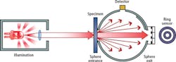
The transparency of the cornea is influenced by the way in which it absorbs and scatters light. To measure the transparency, the haze-gard plus system employs a laser beam which strikes the specimen before entering an integrating sphere (Figure 5). The light, uniformly distributed by a matte white coating on the sphere wall, is then measured by a detector. Total transmittance is measured with the sphere outlet closed, and haze (or loss of contrast) is measured with the outlet open. A ring sensor in the outlet opening of the system also measures the see-through quality or clarity of the light.
If the system determines that the cornea has met a set of predetermined parameters, the embedded PC in the system sends a pass signal to the Arduino processor. If not, a fail signal is generated. Depending on the result of the analysis, the processor then instructs the motion controller to move the gripper over to a chute to where the part is accepted, or to a fail chute where it is rejected. Having completed the inspection operation, the processor then instructs the motion controller to return the gripper to the home position where a new part can be manually loaded into the gripper prior to further inspections.
To enable the system to be to be controlled by an unskilled operator and allow an administrator to modify a variety of system parameters, engineers at LG Motion developed a graphical user interface (GUI) front-end program using Visual Basic.
For the unskilled operator, the GUI displays a number of status panels which each denote the current state of the machine. The HMI touch-screen displays the various stages of execution of the process-whether the part is to be loaded by the operator, when the machine is automatically locating the cornea and its scaffold, and when the laser inspection system is inspecting the cornea for transparency. The screen also displays whether a part has passed or failed the inspection process and prompts the operator to load another package (Figure 6a).

The system administration screen, on the other hand, is used by a skilled technician to allow the system defaults to be configured. Here, the user can set a variety of parameters, such as the speed and accelerator of the motors used to convey the package through the system, configure the coordinates of the camera, the laser in the system and the locations of the pass and fail reject chutes. From that screen, the user can calibrate the system to ensure that the center location of the camera is aligned with the center of the laser measurement machine (Figure 6b).
Since it was developed, the semi-automated inspection machine has now been shipped to Oxford MEStar's production and research facility in China, where it is now enabling operators to inspect the quality of the corneas that it produces.
Gary Livingstone, Managing Director, LG Motion, Basingstoke, Hampshire, UK (www.lg-motion.co.uk)
Companies mentioned
Arcus Technology
Livermore, CA USA
www.arcus-technology.com
Arduino
Somerville, MA, USA
www.arduino.cc
BYK Gardner
Geretsried, Germany
www.byk.com
LG Motion
Basingstoke, Hampshire, UK
www.lg-motion.co.uk
Oxford MEStar
Oxford, UK
www.oxford-mestar.com
Scorpion Vision
Lymington, Hampshire, UK
www.scorpionvision.co.uk
Tordivel
Oslo, Norway
www.tordivel.no
The Imaging Source
Bremen, Germany
www.theimagingsource.com