Lens choices proliferate for developers of machine vision systems

While understanding optical fundamentals is important, so too is a knowledge of the different types of lenses that are available.
Obtaining high-contrast, high-resolution images is especially important when developing a machine vision or image processing system. Without high contrast, the features of interest may not be discernable and, if the captured image is not of high-enough resolution, then parameters of objects may not be measured correctly.
While lighting plays a key role in ensuring that image contrast is maximized, the optics, lenses and image sensors used in such systems must be carefully chosen to ensure that the required resolution will be obtained. Just as choosing a high-performance lens with a sensor with large pixels will not result in a high resolution image neither will choosing a low-performance lens with a sensor with smaller pixels. However, by carefully balancing these two factors, the optimum lens/sensor combination can be chosen to meet the resolution required.
Sensor resolution
Confusingly, many manufacturers cite the resolution of their sensors as the number of active pixels on the device. On its website CMOSIS, for example, states that "the CMV20000 is a CMOS image sensor with a resolution of 5120 x 3840 pixels." This of course, only gives the reader the total number of pixels in the horizontal and vertical direction of the sensor array, and is not an accurate measure of the resolution that may ultimately be obtained using a camera that incorporates the device.
Clearly then, the resolution will depend on the pixel size of the image sensor, and can be calculated in line-pairs/mm (lp/mm) as: 1000 (lp/mm)/2 x pixel size (μm). Thus, for the CMV20000, with a 6.4 x 6.4 μm2 pixel size, the limiting sensor resolution will be 78.125 lp/mm. Therefore, the smaller the size of the pixel, the greater the theoretical maximum achievable resolution.
While a useful measure of the resolution and one that can be used to match the correct lens with the image sensor, systems developers would much rather like to know the resolution of an object that can be achieved with any sensor/camera combination in microns, a resolution that depends on the field of view required, the sensor and pixel size. In the case of the CMV20000, for example, the size of the sensor is given in terms of its optical format which is 35mm.
Such formats are not particularly useful since they do not describe the horizontal and vertical measurements of the sensor. However, since the number of pixels in the image sensor and the pixel size is usually specified, both the horizontal and vertical dimensions of the image sensor can be calculated. For the CMV20000, the horizontal and vertical dimensions can therefore be calculated as (6.4 x 5120)/1000 and (6.4 x 3840)/1000 or approximately 32.7mm (horizontally) and 24.6mm (vertically).
Knowing the sensor and pixel size, the maximum achievable object space resolution at a specific horizontal field of view can then be calculated in microns as a product of the maximum achievable resolution (in lp/mm) and the ratio of the horizontal sensor size to the horizontal field of view. Thus, for a field of view of 200mm, the resolution in line-pairs/mm, using the CMV20000 will be [78.125 lp/mm x (32.7/200)] or 12.77 lp/mm. This can then be represented in microns as [(1/12.77) x 1000] or approximately 78μm.
Focal lengths
The ratio of the horizontal sensor size to the horizontal field of view, or primary magnification (PMAG) can also be used to determine the focal length of the lens required once the distance of the object from the sensor is known. Since the focal length = object distance/ [1 + (1/PMAG)], an object placed 300mm away from a camera employing the CMV20000 sensor, that is required to capture an image with a 75mm field of view will therefore require a lens with a focal length of 300/[1+1/(32.7/75)] or approximately 91mm.
To gain the best performance for any lens/sensor combination, lens parameters must be evaluated. Because light is diffracted when it passes through a lens, an Airy disk pattern is produced. The diameter of this is theoretically the smallest spot size that can be resolved and is related both to the size of the lens' aperture and the wavelength of light used. Thus, using a 510nm green light in a machine vision system, and a lens aperture of f#/16, the smallest spot size that can be resolved will be (2.44 x 510 x 16)/1000 = 19μm, where the constant 2.44 is derived from the Rayleigh criterion (see "Angular Resolution,"http://bit.ly/2ac4Er6).
With a perfect lens, it is obvious then that the smallest spot size is far larger than the pixel sizes of 6.4 x 6.4μm (as is the case with the CMV20000). However, stopping the lens to an aperture of f#/1.8 will result in a theoretically achievable spot size of 2.2μm, smaller than the pixel size of the sensor but at the same time increasing the amount of light delivered to the sensor as well as reducing the depth of field of the camera/lens combination. Thus, to achieve the optimal resolution, lenses should be chosen with an Airy disk diameter that is slightly lower than the pixel size of the sensor.
Lens performance
While the wavelength of the light and the lens aperture tend to play a key role in determining the smallest spot size that a lens can resolve, so too does the performance of the lens. Inexpensive lenses built for CCTV systems very often do not have the performance of those that are built especially for machine vision and image processing systems. Despite what many a marketing manager may claim, there are no such thing as "5M pixel lenses" since lens specifications are never specified in pixels!
To understand how to evaluate the performance of such lenses and whether it will be suitable for a camera based on any specific sensor, the Modulation Transfer Function (spatial frequency response) should be evaluated. While only few manufacturers produce these curves for their products, they offer an easy way to evaluate the performance of a lens. The MTF of a system is represented as a graph that shows how well the lens transfers contrast at a particular resolution (in line pairs/mm) from the object through the lens to the image sensor.
For a perfect lens, the MTF will be 1.0 at zero line pairs/mm. However, as the resolution of the object being imaged increases (in line pairs/mm), the ability of the lens to properly resolve this resolution will decrease. The MTF chart will be dependent of the aperture of the lens, the frequency of the light used and how the MTF is measured. In many cases, the lens is tested at the widest aperture. Sometimes, the frequency of light is stated.
Sensors and lenses
To obtain the most cost effective lens/sensor combination, both the sensor and lens characteristics should be compared. In the case of the CMV20000 image sensor for example, the limiting sensor resolution will be 78.125 lp/mm. Therefore, choosing a lens that resolves a larger resolution than the resolution required by the system is not particularly useful and probably will add to the cost.
Increasing sensor sizes can also add to the cost of a camera/lens combination since larger lens mounts will be required. However, by understanding the resolution needed to resolve an object in any particular vision system application, developers are able to choose the correct sensor and lens combination at the optimum price.
Large-aperture lenses target biomedical applications
Electrophoresis is one of the most widely-used techniques in biochemistry and molecular biology. It has also been recently used for clinical examinations. Using an electrical field, electrophoresis is used to separate and sometimes purify macromolecules that differ in size, charge, or conformation as they travel in a gel at a speed that is inversely related to their lengths.
After the electrophoresis process, the gel is placed in a dark box with a UV light and a camera. The light produces fluorescence on macromolecules, and the camera captures an image of the separation pattern that occurs. This brightness is so low that a high-resolution camera with a high dynamic range is required.
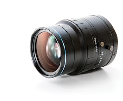
Just as importantly, the lens used must have a small f/# to take a clear image of fluorescent macromolecules since the smaller the f/#, the brighter the image. For such purposes, VS Technology (Tokyo, Japan;www.vst.co.jp) has developed the VS-085 series, a lens with an f/# of 0.85 and focal lengths of both 25mm and 50mm. The lenses support sensors up to 4/3in, and have an M42 mount and C-Mount.
Meng Cheng Wei,President, Tanon Science and Technology Co., Ltd. (Shanghai, China;www.biotanon.com/en/ )
Lenses withstand harsh environmental conditions
Applications utilizing high-resolution, 4K data capture for autonomous vehicles, UAVs, and persistent surveillance systems are growing. Next generation camera modules use real-time algorithms to identify and react to situations in the scene. These computational vision systems use high-resolution, large-format (16mm diagonal) sensors like the Sony Pregius CMOS sensors, and require high-performance optics to obtain the best images possible.
Navitar's new 4K HDR lenses offer superior stray light rejection down to 1E-5, while providing high MTF at the Nyquist frequency of small-pixel sensors. Operating in the visible or visible/NIR waveband at apertures as fast as F/1.8, these new lenses are environmentally robust and perform at military grade temperature ranges of -20°C to +70°C. Additional options such as IP67 sealing allow use in underwater depths up to 1 meter. Optional iris or dual-position electronic shutters allow precise control of exposure levels for day/night imagery.
Even with 4K lenses, maximum performance is only obtained by automated lens-sensor alignment, creating robust camera modules that can survive hostile environments and deliver superior image quality. As such, Navitar will be the first lens OEM to offer actively-aligned lens/sensor modules to our customers in both short run production volumes as well as high production.
Mike Thomas,President, Navitar (Rochester, NY, USA;www.navitar.com)
Compact lens increases high-resolution image distance
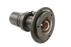
When Laser Technology Inc. (LTI; Centennial, CO, USA;www.lasertech.com) wanted to capture a high-resolution image at a longer range for its 20/20 TruCAM speed enforcement tool, it turned to custom lens design house, SENKO/ADL. The TruCAM design integrates a laser to capture speed, time and distance information with a camera to capture digital video and photographic evidence for enforcement of speeding and tailgating violations, and identify vehicle make, model and license plate numbers.
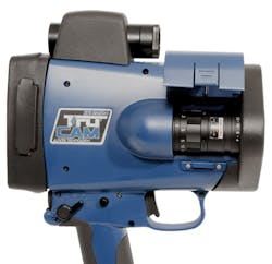
Formerly, the TruCAM had been equipped with a 75mm lens, which allowed operators to enforce speed at long ranges, then track the vehicle up to 70 meters (200 feet) for the high-resolution images needed for chain of evidence and enforcement. But LTI wanted to expand the distance of the high-resolution image to 100 meters (325 feet), without increasing the device's compact size.
Without a readily available solution that could fit in such a compact enclosure and deliver the longer focal length LTI required, SENKO/ADL engineers successfully designed a custom 110mm, 3MP solution, that fit well within the existing TruCAM enclosure, and that would provide a high-resolution image at 100 meters.
Sean Choi,National Sales Engineer Senko Advanced Components / ADL (Marlborough, MA, USA;www.senko.com)
Small format telecentric lenses suit robotic applications
While the optical characteristics of telecentric lenses and illuminators make them the best components for 2D non-contact measurement applications, they are typically large and thus require a large installation space. To overcome this limitation Opto Engineering (Mantova MN, Italy;www.opto-engineering.com) has developed its TC CORE series of telecentric lenses. The biggest design challenge faced when developing CORE series was making them as compact as possible, and ensuring the same level of performances as a classic telecentric lenses. This was difficult since their design has a higher level of complexity compared to classic "cone-shaped" telecentric optics.
Up to 70% smaller than many other telecentric optics, the lenses can be used with 2/3in and 4/3in sensors and allow horizontal FOVs from 26mm to 97mm to be accommodated. Coupling CORE telecentric lenses and illuminators thus allows developers to reduce the size of their vision system, resulting in lower manufacturing, shipping and storage costs. Because of their size, they can also be placed on a vision-based robotic system, allowing more accurate measurements to be made.
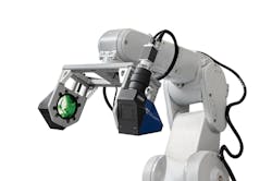
One of the first examples of such a system is the ROBOT-CORE, a prototype system developed by DigiMetrix (Munich, Germany;www.digimetrix.com). The system integrates an optical system consisting of a CORE telecentric illuminator and lens coupled to an acA2500-60um 5Mpixel camera from Basler (Ahrensburg, Germany; www.basler.com) mounted on a RV-4FL robot from Mitsubishi (Vernon Hills, IL, USA; http://mitsubishirobotics.com). For machine vision applications, the system employs both image processing tools based on LabVIEW from National Instruments (Austin, TX, USA; www.ni.com) and DigiMetrix Robotics library for LabVIEW.
Alena Verameyeva,Product Manager, Opto Engineering (Mantova MN, Italy;www.opto-engineering.com)
Minimize longitudinal color aberration
Longitudinal color aberration can be a challenging problem for multispectral applications in which different wavelengths - either simultaneously or sequentially - need to be captured. In these cases, refocusing is often not possible and stopping down the lens to increase depth-of-field is not desirable since more light will be required. Longitudinal color aberration occurs with every lens to a certain degree; however, the extent of aberration depends on the degree of correction. In the design of its Qioptiq MeVis-C f#1.6/25mm traffic lens, Excelitas Technologies (Waltham, MA, USA;www.excelitas.com) has optimized the part for imaging both white and NIR light ensuring that the focal plane for both wavelengths is identical. This eliminates the need for expensive low-dispersion glasses and makes multispectral applications with a fully open aperture possible. The MTF curves in the image show the MTF for 550nm and 850nm wavelengths.
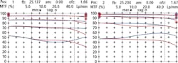
Commonly used for traffic monitoring, the lens images white daylight with a peak at green light during daytime, and NIR at around 880nm at night. The lens is also suited for other multispectral applications such as verification of documents with special security features that must be imaged in visible and NIR light.
Thomas Schäffler,Business Manager - Vision Technology at Qioptiq, An Excelitas Technologies Company (Waltham, MA, USA;www.excelitas.com)
Three-piece lens design targets flexibility
When an off-the-shelf lens is very close to meeting application requirements but doesn't fully optimize image sensor performance, the Cx Series from Edmund Optics (Barrington, NJ, USA;www.edumndoptics.com) might provide a suitable option to close that gap. For rapid optical system modification, the modular, three-piece design comprises fixed apertures, internal filter holders or liquid lenses.

Changing apertures varies depth of field and allows altering the shape of the aperture to introduce specific aberration control. Integrating filters between the optics, allows system designers to dial in on very specific wavelengths to be analyzed, and can also greatly decrease filter size to reduce overall system cost.
Liquid lenses can be integrated directly into the lens assembly for dynamic focus control, and the modular design allows for individual lens elements of the system to be modified to potentially obtain higher levels of resolution at a specific working distance.
Greg Hollows,Director, Imaging Business Unit, Edmund Optics (Barrington, NJ, USA;www.edumndoptics.com)
Companies mentioned
Basler
Ahrensburg, Germany
www.basler.com
DigiMetrix
Munich, Germany
www.digimetrix.com
Excelitas
Technologies Waltham, MA, USA
www.excelitas.com
Mitsubishi
Vernon Hills, IL, USA
http://mitsubishirobotics.com
National Instruments
Austin, TX, USA;
www.ni.com
Opto Engineering
Mantova MN, Italy
www.opto-engineering.com
VS Technology
Tokyo, Japan
www.vst.co.jp
About the Author

Andy Wilson
Founding Editor
Founding editor of Vision Systems Design. Industry authority and author of thousands of technical articles on image processing, machine vision, and computer science.
B.Sc., Warwick University
Tel: 603-891-9115
Fax: 603-891-9297