Vision-based laser welding system helps check medical products
A vision-based, laser-guided welding system is helping improve the reject rate of the welded parts on a medical device.
Eric Speitel, and Mike Updike, Invotec Engineering
By deploying vision-guided laser welding systems, device manufacturers can increase weld quality, consistency, and throughput while simultaneously reducing scrap. In the medical device industry, the use of automated machine vision and image processing systems can help many manufacturers to address complex welding problems where the combination of tolerance stack-ups, beam diameter, and feature size would otherwise cause inconsistent, flawed or unusable welds.
When one medical device manufacturer was faced with automating the manufacture and inspection of a medical device, it enlisted Invotec Engineering (Miamisburg, OH, USA; www.invotec.com) to develop a vision-based welding and inspection system specifically for the purpose. The automated system was created to replace an older, purely mechanical system that the company had deployed and which had suffered from a component reject rate of greater than 58%.
The vision-based laser welding system automatically welds the leads of a temperature sensor to an extension cable which is then attached to a medical device later in the production process. To do so, the system presents both leads from the sensor and the cables to a welding station where a vision system locates the leads and then positions the laser to the optimum position for the welding process. After the two leads have been welded together by a laser, the vision system inspects the leads to ensure that the welded joint falls within specific tolerances.
On the track
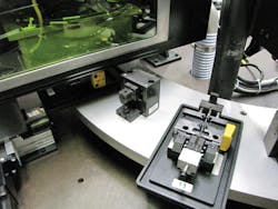
The system consists of eight stations with automatic operations positioned around an indexing rotary dial transport system. A cam-operated, motor-driven indexer and dial plate assembly are used to synchronously transfer the components being put together through the correct sequence of steps, which ocurr at each station (Figure 1).

At the first of these stations, the temperature sensor is automatically removed from a bulk tape reel and placed into a nest on the outer edge of the dial by an automated pneumatic pick-and-place mechanism.
The indexer then proceeds to move the nest to the second station where the leads of the temperature sensor-which can typically vary in length-are trimmed to the required length by a pneumatic cutter which is brought down on top of the fixture holding the sensor.
Having trimmed the leads to the required length, the fixture holding the sensor is indexed to the third station where a second nest is loaded with the cable subassembly.
Rather than directly loading the cables to the assembly nest on the dial, the operator loads ten cables onto a separate indexing conveyor which consecutively carries each of them to an automated pick-and-place on the assembly dial. As the pick-and-place transfers the cable from the indexing conveyor to the assembly nest, a sensor locates the end of the cable so that it can be accurately placed to the nest.
At this stage in the assembly process, the two cable leads must be crimped flat so that when they are brought into contact with the leads from the sensor, they are correctly positioned so that the optimum weld will be formed. To do so, a pneumatically-actuated press tool is brought down onto the end of the leads to flatten them. Once flattened, the crimping tool is retracted, and the nests holding the sensor and the cable are brought together at the fourth dial station, such that the leads from the sensor are presented directly above the leads from the cable.
Vision system design
Once the leads in the nests have been brought together, they are then ready to be welded together. Prior to the welding operation, however, the location of the leads must be identified by the vision system so that the laser can be accurately positioned for the weld operation. If the leads are too far out of position, the machine will index the parts around to a reject station on the machine where the parts will be scrapped.
After having welded the parts, the machine vision system then checks the appearance of the weld. If the two pairs of leads appear to have been welded correctly, then the parts will continue around the rotary dial where they will be passed over to another assembly system where further processing and assembly will be carried out. If not, the parts will be rejected.
The pairs of leads are welded together by a vision-guided laser welding system that is housed in a protective shroud that is brought down to enclose across the entire station prior to welding. The shroud performs three important functions. First, it protects an operator from any potential exposure to harmful laser radiation. Secondly, it enables the leads from the sensor and the cable to be flooded with inert argon gas prior to welding to reduce any oxidation that may occur during the welding process. Lastly, it allows any fumes or debris that may occur during the welding process to be extracted.
The vision system housed inside the enclosure comprises an In-Sight 1403 smart camera from Cognex (Natick, MA, USA; www.cognex.com) running custom software developed using Cognex In-Sight Explorer and an evenly diffused dome light from Advanced illumination (Rochester, VT, USA; www.advancedillumination.com) that is used to illuminate the leads with cloudy day lighting during the image acquisition process.
A 50W YAG laser from Amada Miyachi Unitec (Monrovia, CA, USA; www.amadamiyachi.com) is contained in a separate unit some meters from the station. The laser light from the station is fed across a fiber optic cable into a laser head mounted on a servo system, enabling the head to be moved to the precise location where the welds needs to be formed.
Once the shroud has been positioned over the two nests, the In-Sight smart camera captures an image of the pairs of leads to determine the location of both the sensor leads and the cable leads with respect to one another. This data can then be used to determine where the optimum weld should be made.
The pairs of coordinates of the welding positions are then transferred from the camera to the Allen Bradley PLC which instructs the two servos onto which the laser head is mounted to move consecutively to each of those positions where the laser is fired and the two pairs of leads are welded together. Once the welds have been formed, a second image of the welded joints are captured and analyzed to inspect for any defects.
Lead location
To determine the location of the sensor leads and the cable leads prior to welding, the image captured by the smart camera is analyzed by the In-Sight software. In the process, the software first uses a specific feature of the nest as a reference point in the image from which a region of interest (ROI) containing the two sets of leads can be derived. Once the ROI has been determined, a set of filters is applied to the image to provide a consistent image that has high contrast in the areas in the image where the leads are present.
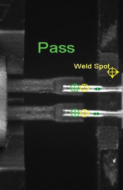
From the images of the pairs of leads, the system software can determine if the two pairs of leads are co-located (Figure 2). If the leads from the sensor are not located above the leads from the cable to within a specific set of tolerances, the process will terminate at that point, and the welding process will be aborted. The part will then be flagged as a reject by the vision system which will be discarded at a reject station later in the process.
Once the ROI has been located and defined and the images processed to locate the leads, edge detection tools are applied to find the center of the end of each of the cable leads. A similar process is then performed to find the center of the end of the leads of the sensor. To ensure an optimum weld between any pair of leads, the weld itself is actually formed between each of the two pairs of leads at a specific distance from the ends of each of them.
Given the known location of the ends of the leads, the software can perform this offset calculation to determine the precise location where the weld is to be made.
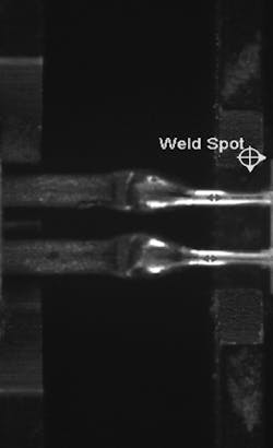
After the laser has performed the welding operation by fusing the two pairs of leads together, the weld itself must be inspected to ensure that it has been formed correctly (Figure 3). Once again, the camera captures an image of the parts, and a fixture is located from which a ROI in the image can be located where the weld was formed. Filters are again applied to highlight distinct features of the weld itself.
Ball weld detection
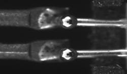
One specific defect that the manufacturer was interested in determining was the presence of ball welds. If a sensor lead does not lie directly on top of the lead from the cable, during the welding process, the laser will ablate the sensor lead but, due to the distance in height between the two, will not form an effective weld. In this case, the laser energy melts the sensor lead, forming a small sphere of molten material.
To determine whether an acceptable joint has been formed between the leads, or to ascertain whether a ball weld is present, In-Sight software tools were deployed to analyze the images of the welded joints (Figure 4).
If the smart camera detects that a ball weld is present either using edge detection or pattern matching tools, the camera flags the PLC to highlight that the weld is unacceptable. The part then is rotated around the machine to a reject station where it is rejected. Good parts are conveyed around the dial where they are handed off to a second automated assembly station where further assembly operations are performed to complete the medical device.
The entire vision-based assembly system took almost a year to develop and has now been running effectively at the medical device manufacturer for over six months. During that time, the system has proved effective at reducing the percentage of parts that are scrapped from 8% to 1.5%.
Eric Speitel, Senior Account Manager and Mike Updike, Controls Engineer, Invotec Engineering (Miamisburg, OH, USA; www.invotec.com)
Companies mentioned
Advanced illumination
Rochester, VT, USA
www.advancedillumination.com
Allen Bradley
Milwaukee, WI, USA
http://ab.rockwellautomation.com
Amada Miyachi America
Monrovia, CA, USA
www.amadamiyachi.com
Cognex
Natick, MA, USA
www.cognex.com
Invotec Engineering
Miamisburg, OH, USA
www.invotec.com