Mechanical and vision component tolerance allocation is important for any process that requires precision and validation.
Bhaskar Ramakrishnan
Metrology is an important part of any process that requires precision and validation. Metrology can be applied to parts, sub-assemblies and final assemblies. A few examples of applications where precision metrology is used include: Post-assembly inspection, incoming inspection of parts to verify supplier quality, binning of parts so they can be used for selective assembly, and process verification like measuring the dispense volume and position of adhesives.
The process starts with understanding the application, parts and assemblies that are required and understanding the Manual Standard Operation Procedure (MSOP).

The scope of this article is to discuss, from an inspection equipment design perspective, the process of allocating tolerances to the mechanical and vision system components for a given part's dimensional tolerance.
Measurement System Analysis (MSA) is a process that is applied throughout the world to qualify metrology systems and is the basis here too. There are two components to the MSA, 1) Gage variation and 2) Part-to-Part variation. The part-to-part variation is something that cannot be controlled by the metrology equipment manufacturer. However, the measurement system can be architected so that its error contribution to the measurement tolerance (% Tolerance for Gage R&R) is within the AIAG (Automobile Industry Action Group) recommended limits (see Table 1).


The 5.15 multiplier on standard deviation is used for 99% coverage of the normal curve. For 99.73% coverage the multiplier needs to be changed from 5.15 to 6.0. An illustration of part and measurement error is shown in Fig.2. Note that the tolerance range is the difference in Upper Specification limit (USL) and Lower Specification Limit (LSL).
The inspection machine's architecting process starts with understanding the customer's requirements. The tolerance of dimension that needs to be measured with respect to the datum needs to be understood. In general, a good gage is deemed to be within 20% Gage R&R tolerance.
Applying 20% as the acceptable % gage error to Equation 1, we can calculate the standard deviation of the gage:

For a system that uses vision for inspection, this is the total allowable gage error that has to be allocated to the vision and part location fixture. In general, while allocating the tolerance, the minimizing function is cost. This means the tolerance allocation should not be a severe constraint to neither the vision nor the stages and nest that are locating the part.

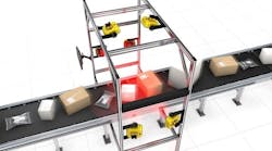
Equation 3 is the fundamental building block for the system-level error allocation and needs to account for all the major sources of variation. Note that part position error is contributed from the 6° of freedom of the part with respect to the camera location. Most of this can be accounted for by having a reference feature in the camera field of view (FOV).
It is usually preferred that the feature measured is within the FOV, as it minimizes fixture error contribution. If this is not possible, then the next ideal scenario is to have multiple cameras cover the region of interest. Here we need to consider the camera-to-camera error contribution. The last scenario would be to add motion so that either the camera or the part moves to cover the region of interest. In this case, the motion error (camera-to-fixture error) has to be accounted for.
There are other elements such as machine-to-machine variability that we are not considering here. For example, if the plan is to replicate machines, then estimates for the machine-to-machine (camera-to-camera) and nest-to-nest (location-to-location) variations must be added to the right side of equation 3.

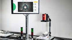
The selection of the camera is based on the application. Specific camera parameters such as depth of field and field of view need to be determined based on the features that need to be evaluated. Eventually this condenses down to resolution or microns per pixel. The rule of thumb for pixel size is 1/60 of the tolerance range.
In general, if a high contrast image with feature in good focus is obtained, we can apply sub-pixel interpolation and reduce the number of pixels required. An illustration of this concept is shown in Fig. 3. The image on the left shows high contrast image in good focus. The image on the right has low contrast and is not in focus. In order to obtain a similar resolution as the left side image, the right side image must have many more pixels.
Once the vision system (camera, lens, and lights) is selected, a quick test is performed to validate the. σCamera R&R.
Using equation 3, we can then estimate the allocation for part position as:

The allocation for part position (σPosition R&R) is then compared to the sum of the dimensional tolerance analysis (from camera-to-part) and motion system (stages, motor, and part snugger) variations. A margin of safety (~10%) is added to capture all other noise factors.

Bhaskar Ramakrishnan, Technical Sales Engineer, DWFritz Automation, Inc., Wilsonville, OR, USA (www.dwfritz.com)
Companies mentioned
DWFritz Automation, Inc.
Wilsonville, OR, USA
www.dwfritz.com