Production and packaging : Vision system controls painkiller packaging process
Mucoadhesive buccal film (MBF) containing medicinally-active ingredients has become a promising dosage form for pain killer delivery. Because the medicinally-active ingredients transport through the mucous membrane lining the inside of the mouth, such drug delivery methods avoid first pass metabolism, gastrointestinal side effects and can provide rapid onset of action. However, what patients ultimately remove from the packaging and put in their mouths must meet strict quality requirements. Harro Höfliger (Allmersbach im Tal, Germany;http://www.hoefliger.com) designs and builds MBF production and packaging plants. Now, teaming with Stemmer Imaging (Puchheim, Germany; www.stemmer-imaging.com), the company has developed a machine vision system comprising three image processing modules to ensure reliable quality inspection.
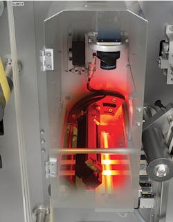
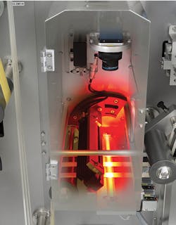
The first inspection station checks that the printing is correct on the front side of all three active ingredient strips with a maximum speed of 1050 parts per minute.
With the active ingredient evenly distributed in the laminate, the medicament dosage is controlled by the size of the MBF, explains Hartwig Sauer, head of the machine vision team at Harro Höfliger. During operation, the MBF production and packaging machine removes the protective film, prints dosage data on the web, cuts the web into individual doses and finally seals them in aluminum composite foil bags.
The first inspection station checks that the printing is correct on the front side of all three active ingredient strips with a maximum speed of 1050 parts per minute or almost 18 parts per second – on each of three webs. Paired with an APO-Componon lens from Schneider Kreuznach (Bad Kreuznach, Germany;www.schneiderkreuznach.com), a Spyder3, 4k line scan camera from Teledyne DALSA (Waterloo, ON, Canada; www.teledynedalsa.com) acquires images across all three strips and 150 mm beyond. Red LNSP line lighting from CCS America (Burlington, MA, USA; www.ccsamerica.com) provides the appropriate illumination.
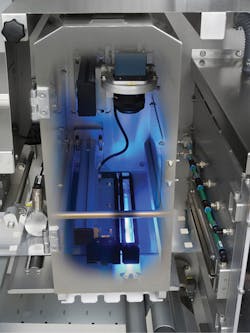
The positions of the separated products are checked at the second image processing station.
Next, a rotary die cutter cuts the final product out of the three webs, which are transferred to the lower packaging film by means of vacuum before the products are placed on the carrier material in three rows with correct longitudinal and transverse spacing. The second inspection station uses another Spyder3, 4k line scan camera with APO-Componon lens, but requires blue LNSP line lighting with coaxial attachment from CCS for optimum illumination of the strips. The blue lighting provides sufficient contrast with the background to perform three vision tasks. First, the position of the separated products are checked to ensure that the subsequent sealing process can proceed. Next, product size is confirmed, and finally, the system inspects for contamination down to a size of about 1 mm².
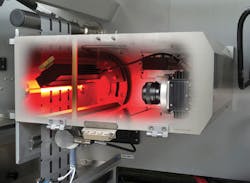
The third image processing station checks the printing of the upper packaging material web, reading the production data, shelf life, batch number and packing material number in the form of a 2D matrix code.
A third image processing station inspects pre-printed production data, shelf life, batch number and packaging material number in the form of a 2D matrix code on the upper packaging material. The linear image data of all three image processing stations are transferred to a specially assembled computer in which a microEnable IV frame grabber from Silicon Software (Mannheim, Germany;https://silicon.software) buffers the incoming line data, assembles them into complete images and then evaluates the images.
"This part of the task was extremely demanding, because the images are captured with an overlap beyond the individual products," say the responsible application engineers Achim Hasmüller and Goran Tambolas from Harro Höfliger, explaining the particular challenges. "Each image consists of the end of the preceding product, the complete current product and the beginning of the following product. In this way we were able to ensure that errors at the interfaces between two products are also detected reliably."
Since all captures are triggered, the positions of all faulty products in the process can be tracked precisely in the machine’s internal shift register and discharged at the end. Following various unsuccessful attempts with other technologies, the machine vision team from Harro Höfliger were able to solve this processing task with a frame grabber in combination with the Visual Applets software environment from Silicon Software. A computationally-intensive part of the image processing is done by an FPGA on the frame grabber, thus reducing the industrial PC’s CPU load through suitable image preprocessing.


