3D imaging: 3D vision system detects gear defects fast
While accuracy is critical for gear inspection, in production, inspection speed can make all the difference. If a gear manufacturer produces a gear in a minute or less, but it takes several minutes to inspect each gear, every gear may not be inspected. It goes without saying that if this is the case, many defects may not be identified until after the gearbox is assembled and tested. This is an expensive proposition for gearbox manufacturers because of the resources required to disassemble the faulty gearbox and identify and replace the faulty gear.
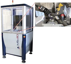
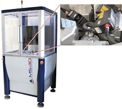
Understanding this, Mesure-Systems3D (MS3D; Bruz, France;www.ms3d.eu/en/) has developed a non-contact 3D scanning system to perform 100% in-line inspection of gears right on the shop floor. The system, dubbed GearINSPECTION, was previewed at last year's VISION 2016 tradeshow and conference in Stuttgart, Germany.
"Basically, a gear, depending on the plant and the type of gear, is produced every 10-40 seconds. That's the cycle time," explains Dr. Marc Rosenbaum, President of MS3D. "And the tactile measurement systems currently in use have a measurement cycle time of 5-6 minutes. So there is a pretty big gap between 40 seconds and 6 minutes. In our system, handling of each gear takes 30 seconds or less."
The metrological core of the machine on exhibit was designed for 3D geometrical inspection of pinion gears that have a 3-mm minimum internal ring diameter, an 80-mm maximum external ring diameter and a height ranging from 1 to 25 mm. For this size part, the machine uses five LJ-V7060 3D laser displacement sensors from Keyence (Itasca, IL, USA;www.keyence.com) to scan the gear in less than two seconds, collecting millions of data points.
"We are presently developing a system that will measure gears up to 40 mm in height," notes Rosenbaum. "However, this requires at least 7 sensors and the Keyence sensors are too bulky to fit within the core of the machine." Consequently, to achieve this capability MS3D engineers have specified more compact 2700 series laser sensors from Micro Epsilon (Ortenburg, Germany;www.micro-epsilon.com), which are small enough to fit into the machine.
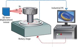
For the five-sensor system, one laser displacement sensor scans the central bore and another four scan the flanks of the gear with two sensors required for each side of the gear teeth. In production, pinions would typically be loaded onto a tripod in the center of the metrological core using a robot or manually.
"It typically takes four seconds to load and unload the gear," explains Rosenbaum. The gear is then rotated as the sensors simultaneously scan the gear from various positions and angles. It takes about two seconds to stitch these images together into a single 3D point cloud. For a standard gear, 12 to 18 million points are generated, and from these, geometrical features are extracted within 20-30 seconds.
One issue that MS3D encountered was that different companies have different standards for how they want the data presented. Rather than developing a unique graphical user interface (GUI), MS3D integrates Quindos, a third-party software from Hexagon Metrology that is used as a front end.
"We tested many software products on the market, and this was the only one which was at the same time universal and able to quickly interface with our own software," said Rosenbaum. "The real bottleneck comes from the fact this software is geared for 2D input from tactile machines, not 3D data. However, this software allows us to present the data the way the customer wants it."
Geometrical features or surface aspect defects are directly extracted from the dense cloud of points using specific software developed by MS3D. The software compares the scan data to dimensions extracted from CAD models or 2D drawings to measure specific areas of interest and determine if it is within tolerance or not. A final report is created showing the measurement analysis performed on each part.


