Industry Solutions: Smart camera checks currency for counterfeits
Open-source software and modular embedded hardware facilitates the rapid development of systems to detect counterfeit banknotes.
Dr. Ricardo Ribalda
Traditionally, many systems builders have developed custom vision applications using off-the-shelf Windows-based PC hardware and vendor supplied software libraries. However, there is a growing trend to use less expensive embedded systems hardware, open-source operating system software such as Linux, and open-source image processing libraries such as OpenCV (www.opencv.org).
To demonstrate how such an industrial machine vision application can be built quickly and efficiently using embedded systems and open source software, Danish camera vendor Qtechnology (Valby, Denmark;www.qtec.com) recently teamed with Advanced Micro Devices (AMD; Sunnyvale, CA, USA; www.amd.com) and Mentor Graphics (Wilsonville, OR, USA; www.mentor.com).
Using an industrial camera based on AMD's R series system-on-chip (SoC, formerly codenamed "Merlin Falcon") running Mentor Embedded Linux operating system, Qtechnology has developed a system to perform high-speed scanning and validation of paper currency.
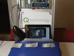
The application highlights how counterfeit notes can be identified by scanning the currency with a light source having a specific spectral range, capturing images of the banknotes with a Qtechnology camera and then checking the resulting images (Figure 1). To achieve real-time performance, the software was analyzed and optimized using Mentor Embedded Sourcery CodeBench and Integrated Sourcery Analyzer to identify and resolve functional and performance issues.

Cameras and software
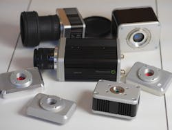
Qtechnology cameras are modular in nature and comprise a number of heads into which a variety of CMOS, CCD, InGaAs, and microbolometer sensors can be mounted. There is also a variety of camera bodies, ranging from a pure FPGA system (QT5012) to their brand new system containing two main computing units (QT5122): a FPGA and an AMD's R series SoC, which features four Excavator x86 CPUs cores with a Radeon graphics GPU and an I/O controller on a single die. The modular nature of the system enables developers to mix and match the heads with the bodies to meet the needs of their application (Figures 2a and 2b).
The FPGA inside the camera controls the sensor's settings, processes the images and transfers captured images over a PCIe interface. Several operations are performed by the FPGA such as image, white balance, perspective and illumination correction, thus offloading the main CPUs of the task.
Once images have been pre-processed by the FPGA, they are transferred over a PCI Express Gen2 x4 interface to the R series SOC. If further computing power is required, an additional GPU can be added within the body of the camera. However, for most applications, the computing power of the R series SOC is sufficient.
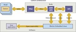
Accessing the functionality of the GPU compute units in the system is achieved through the Open Computing Language (OpenCL), an open standard maintained by the non-profit technology consortium Khronos Group (Beaverton, OR, USA;www.khronos.org) for programming and executing programs on devices such FPGAs, CPUs and GPUs. Similarly, the functionality of the image sensor can be accessed through Video4Linux (www.linuxtv.org), a collection of device drivers and an API for supporting video capture on Linux systems. This enables parameters such as the image resolution and the frame rate to be controlled, freeing the user from using proprietary libraries.
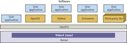
Because of the open architecture of Qtechnology's platform, a developer has many programming options to choose from (Figure 3). First, an application could be created simply using C or C++ . Secondly, open source software such as GStreamer (https://gstreamer.freedesktop.org) could be deployed to process image data by connecting a number of proprietary or third-party image processing plug-ins to create custom pipelined software. Thirdly, programs could be developed using libraries of image processing functions written in Open CV or Python, or by reusing functions from third-party libraries such as MATLAB from MathWorks (Natick, MA, USA;www.mathworks.com) or HALCON from MVTec Software (Munich, Germany; www.mvtec.com).
Banknote characteristics
Before writing any application software, however, developers must be aware of the characteristics of the inspected product, based on which the choice of camera and light source technologies will be affected. Due to its modular nature, this is an easy task with Qtechnology cameras. The vision researcher will develop a single application and then experiment with the different heads/sensors, reducing dramatically the time to explore the solution space.
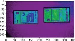
To discern between real and counterfeit banknotes, it was determined that under infrared (IR) light, only the emerald number, the right side of the main image and the silvery stripe are visible on the front of the banknote. On the reverse side, only the numerical value and the horizontal serial number are visible (Figure 4).
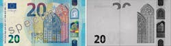
Hence it was decided to illuminate the banknotes using a halogen lamp as a source of IR light and to capture the images using a Qtechnology monochromatic CMOS camera -a Qtec QT5122 body with CMOSIS (Antwerp, Belgium;www.cmosis.com) monochrome IR enhanced 2MPixel head-fitted with an IR filter. Images captured by the camera of the real Euro note will have all the left part of the details missing, while in the counterfeit note, the details will still be clear. This is because Euro notes use an ink that absorbs IR light, whereas counterfeit notes (possibly photocopied) reflect IR wavelengths.
Once the hardware for the system has been selected, images of the banknotes can be captured from the camera and image processing software can be developed. To facilitate the programming of the camera, Qtechnology has developed a web-based interface that enables the camera to be programmed remotely (Figure 5). The web-based tool accesses the hardware of the camera through the Video4Linux interface and allows easy navigation through tens of settings, such as the bit mode of the sensor, the response curve, the triggering mode and the color map.
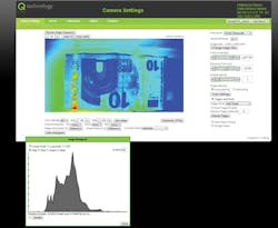
By using the web-based tools, a region of interest (ROI) in the image of the Euronote can be selected where details of a legitimate note should not be visible when the note is illuminated by IR light. These tools also enable the frame rate of the system to be set in software. It is possible, of course, to analyze the whole image of the note in software. However, by using a smaller ROI, the maximum frame rate (up to more than 1000 fps) of the system can be achieved. Thanks to the PCIe Gen2 x4 link to the APU, up to 2 GB/s of data can be received by the body.
Once the images have been sampled, they can either be saved in a JPEG or in a lossless format. To analyze the images, the developer can use Jupyter Notebook (http://jupyter.org). This enables programmers to create and share documents that contain live code, equations, visualizations and explanatory text. Using the Notebook, a developer can program the embedded system in the Python programming language, which in turn provides access to both Open CV (http://opencv.org) and NumPy/SciPy (www.numpy.org) image processing libraries, enabling them to be combined in a single program.
Banknote identification
In the case of banknote identification, the algorithm was easily implemented using the Jupyter Notebook interface. The first stage of the image processing chain involved locating the edges of the notes by applying a Canny filter (http://bit.ly/VSD-CANNY) to the images of the Euronotes. The numerical values for the upper and lower thresholds were calibrated using static interactive widgets, or, sliders.
With the edge detection performed, a filling algorithm was selected and applied to fill out all closed regions in the images, after which the contours of the notes were detected to determine the specific location of the notes within the image (Figure 6).
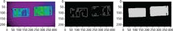
Once the position of a note was determined, a ROI was located inside the image corresponding to the location of features of a legitimate bank note. These would be invisible when the note is illuminated by the IR light source (Figure 7).
Because features on legitimate notes are effectively invisible in the ROI, analyzing this region can determine whether the note is real or counterfeit. To do so, a simple threshold classifier was applied to determine the number of pixels in the ROI. By setting the thresholds of the classifier in software, it is possible to determine the pixel intensity values under the ROI and then determine the legitimacy of the currency. Having done so, the notes are then labeled to indicate whether they are real or counterfeit.
The system is light dependent, so it is important to ensure that the samples of the banknotes are well illuminated. Because of this, it may be necessary to adjust the threshold of the classifier to accommodate the different luminosity levels used to illuminate the banknotes.
Using the Jupiter Notebook interface, the algorithm can be easily tuned and debugged, showing any intermediate results in a numerical and graphical way.
Code optimization
Once the correct vision algorithm has been developed, it is important to have an implementation that can run at the desired throughput. It is optimized to run efficiently on the embedded AMD R series SoC-specifically to ensure that optimum use is made of the four Excavator x86 CPU cores on the device.
In this case, the implementation was done using Gstreamer (https://gstreamer.freedesktop.org)-a multimedia framework that links together a variety of custom built or off-the-shelf media processing elements called plug-ins into a software pipeline. Hence, the first step in the analysis process involved converting the image processing software into a GStreamer plug-in that was labeled "Euronote".
Using Gstreamer, the off-the-shelf Video4Linux plug-in was used to fetch images into the pipeline from the 2MPixel camera and set the frame rate at 100fps. Then, another Gstreamer plug in was used to send the images to the Euronote plug in, after which it could be scaled to 1024 x 768 into a I420 format (http://bit.ly/VSD-I420) where the images are represented in the YUV.
Once the application was written, Mentor's source analyzer was employed to determine the speed of execution. To do so, the code was copied into the Mentor Embedded Sourcery Codebench from where the binary code could be transferred to the target AMD processor where it was executed. The Sourcery Analyzer then graphically highlights CPU statistics that show the time each core spent in a given state, scheduling statistics that highlight which software threads ran on each core and the thread migration rate, or how frequently the system scheduler moved software threads between cores.
Throughput analysis
The Sourcery Analyzer enables a throughput analysis to be performed on the Euronote Gstreamer application. If the system is not meeting the image capture rate demanded by the application, it is possible to access the Euronote software program from the Sourcery Analyzer environment. This enables the size of the image that is acquired to be scaled down before it is applied to the Euronote application for processing, hence improving the number of frames per second that can be acquired.
However, if scaling the image size still does not effectively enhance the speed of the system, it is possible to enhance performance further by ensuring that all of the four ALUs on the embedded processor are utilized in full. By using the scaling tracer on the Mentor Embedded Sourcery Analyzer, the number of ALUs on the SoC used can be determined.
If the processing power is under used, it is possible to optimize the execution of the program so that multiple threads, or components of the Euronote application, can be run in parallel. To do so, the Gstreamer code can again be accessed from the analyzer and queues created in the software to optimize the pipeline. Once achieved the resulting code can again be executed and profiled using the Sourcery Analyzer (Figure 8).

However, using such a technique is not without its limitations. Having parallelized the code to run on multiple CPUs, it may be that the performance of the system is still less than optimal. Instead of going through the pipeline, images are being copied into the queues, a process which itself introduces some overhead. This can be verified by using the memory allocator tracer in the Sourcery Analyzer and viewing the amount of memory allocated to the process.
This issue can be resolved easily, however, by returning to the Euronote code via the Sourcery Analyzer and ensuring that no image data is stored within the queues during the execution of the Euronote application. Once this has been achieved, the program can be saved, executed again and the results of the execution viewed using the Sourcery Analyzer.
Optimized system
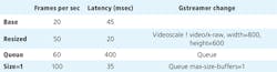
The results achieved by using the Mentor Embedded tools to optimize the performance of the system are summarized in Figure 9. Prior to optimization, the system was only capable of capturing images at a rate of 20fps, while the latency between image acquisition and processed output was 45ms. Having resized the image data, the image capture rate was increased to 50fps with 20ms latency. By introducing a queue to the process, it was possible to improve the system throughput further to 60fps with 400ms latency. Finally, by limiting the maximum size of the buffer, the system captured images at 100fps with 35ms latency.
Undoubtedly, the use of open-source operating system software, libraries of freely available image processing software, coupled with the use of advanced system diagnostic tools and inexpensive modular camera hardware, will continue to provide developers with an inexpensive means by which they can develop machine vision applications. Indeed, the proliferation of such hardware and software may ultimately provide a significant challenge to many existing software-hardware vendors who rely on proprietary architectures.
Dr. Ricardo Ribalda, Lead Firmware Engineer, Qtechnology (Valby, Denmark; www.qtec.com)
Companies mentioned:
Advanced Micro Devices
Sunnyvale, CA, USA
www.amd.com
Khronos Group
Beaverton, OR, USA
www.khronos.org
MathWorks
Natick, MA, USA
www.mathworks.com
Mentor Graphics
Wilsonville, OR, USA
www.mentor.com
MVTec Software
Munich, Germany
www.mvtec.com
Qtechnology
Valby, Denmark
www.qtec.com