Industry Solutions: Smart robot performs vision-assisted surgery

Using near IR and 3D cameras, robots are being used to assist physicians in performing surgery.
Dr. Axel Krieger
While robot-assisted surgery (RAS) has been adopted in many settings, soft-tissue surgery has remained a manual or teleoperated procedure, largely because of the unpredictable changes in soft tissues that may occur during an operation.
Detecting such changes during surgery has been challenging because of both the prior lack of vision systems that distinguish and track target tissues in dynamic environments and the deficiency of algorithms that interpret image data allowing robots to execute surgical tasks autonomously.
Now, however, researchers at Children's National Health System (Washington, DC, USA; https://childrensnational.org) working with colleagues at John's Hopkins University (Baltimore, MD, USA; https://www.jhu.edu) have developed a Smart Tissue Autonomous Robot (STAR) to determine whether complex in-vivo surgical tasks, currently performed by surgeons, can be executed autonomously.
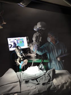
The STAR system (Figure 1) employs a vision system to capture images of markers attached to soft tissue. Using captured image data, an algorithm then creates a suturing plan, highlighting where a row of stitches holding together the edges of a surgical incision should be made. The coordinates of the suture are then transferred to a robot that performs the procedure using an articulated laparoscopic suturing tool.
3D image capture
Tracking features of soft tissue in three dimensions (3D) is not trivial. Organ surfaces are typically smooth and have similar visual appearances, and may be occluded by blood or tissue. For that reason, the STAR system employs near-infrared fluorescent (NIRF) markers placed by a surgeon on the edges of the tissue to be sutured prior to surgery. The STAR system tracks these markers that are then used as reference points to plan suture locations.
The Star system uses two cameras (Figure 2), an NIR camera from Basler (Ahrensburg, Germany;www.baslerweb.com) and a plenoptic 3D camera from Raytrix, (Kiel, Germany; www.raytrix.de). The NIRF markers create high-contrast areas in the 2D NIR images captured by the Basler acA-50gm camera that is fitted with an 845nm bandpass filter from Chroma Technologies (Bellows Falls, VT, USA; www.chroma.com).

To capture a 3D image of the scene, the Raytrix R12 plenoptic camera uses a micro-lens array placed in front of the image sensor. Thus, multiple images captured by the camera are captured from a different perspective. Images generated by the plenoptic camera are then processed on a PC to calculate scene depth and reconstruct a 3D point cloud.
The field of view of both cameras is illuminated by an LED light source from Marubeni America (Santa Clara, CA, USA;http://www.marubeniamerica.com) that emits light at 760nm to excite the markers, making them glow in the image captured by the Basler NIR camera.
The Raytrix plenoptic camera requires less space than a traditional stereo tracker, which is important in a crowded operating room. Also, it reduces the stereo matching correspondence problem of traditional 3D camera systems.
Prior to deployment, both cameras must be calibrated and registered to enable the vision system to translate measurements made in pixels to real world coordinates. This registration process requires both cameras to observe a common checkerboard with known dimensions from which the pose of each camera with respect to the checkerboard, and to each other, can be determined.
After calibration and registration, coordinates of locations of the markers from one camera image can be transformed to another. In the STAR system, a marker is excited by NIR illumination and observed in the NIR image. Locations of the marker coordinates are then transformed into the 3D point cloud image after which the pixel coordinates of the markers are translated to x,y,z metric coordinates (Figure 3).
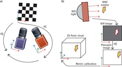
Image tracking
To track the position of the markers, the STAR system employs a 3.4GHz i7-3770 CPU with 4GBytes RAM equipped with an 836MHz GeForce GTX Titan graphics card with 8GBytes of memory. To control image data acquisition from the cameras, the PC runs the Robot Operating System (ROS;http://www.ros.org)–a framework for robot software development. Using the ROS, individual processes–such as image processing and automation tasks–can be partitioned into nodes and the results from each process communicated between them.
To track the NIRF markers, a blob tracker module from the Visual Servoing Platform (ViSP; https://visp.inria.fr/modules) modular C++ library was used. The algorithm first binarizes the image and then performs a contour detection to determine the characteristics of each of the markers.
More specifically, the algorithm determines the coordinates and higher order moments of tracked blobs with high-contrast intensity. If the blob cannot be located due to occlusion of the field of view (FOV) of the cameras by the surgical tool, a bounding box is searched and tracking resumes once the marker re-enters the box.
Corresponding 3D points for each tracked marker is then determined by projecting the point cloud onto the NIR image using the OpenCV (http://opencv.org) function projectPoints and taking the median of all pixels within a five-pixel radius of the blob's center of mass.
The speed of the 3D tracking is limited by the rate at which the plenoptic camera captures images. To resolve the issue, the STAR system software determines the position of the markers in 3D space by calculating the x,y planar 2D coordinate data captured by the NIR camera at a faster rate while the z (depth) data from the plenoptic camera is calculated at a slower rate. The results are then combined to provide the 3D coordinates. The hybrid approach allows the system to track scenes faster and more accurately than either camera would in isolation.
After creating a line of best fit between the tracked positions of the NIRF markers, an algorithm then creates a suture plan. This determines the optimal spacing between the sutures, the number of sutures and how the sutures should be aligned. If the tissue moves during the surgery, the suture plan is automatically updated.
The results of the plan are displayed on a monitor where a surgeon can review the results of the plan and make adjustments to it if required. The visual representation highlights where the robot plans to make different suture types that are used to bind the tissues together such as running sutures, knots, or corner stitches.
Once the coordinates of the sutures have been determined, custom control software developed using Open Robot Control Software (OROCOS;www.orocos.org) determines how each of the joints of the robot must be moved to enable the suturing tool to reach a desired location. The results are then passed from the PC over an Ethernet interface to a robot controller from Kuka (Augsburg, Germany; www.kuka.com) that is interfaced to an LWR4+ lightweight robotic arm fitted with a custom motorized Endo360 suturing tool from EndoEvolution (Raynham, MA, USA; http://endoevolution.com) that performs the suturing operation.
To control the suture tension and limit the force applied to the tissue by the suturing tool, the robotic arm is fitted with a Gamma force sensor from ATI Industrial Automation (Apex, NC, USA;http://www.ati-ia.com) that is placed between the last link on the robot arm and the suturing tool. The use of the force sensor controls each suture tension and ensures that the applied force between the suturing tool and the tissue can be limited so that the tissue is not unnecessarily deformed during surgery.
Robotic results
To compare the effectiveness of STAR to other surgical procedures, a recent study examined the effectiveness of the system in performing end-to-end intestinal surgery on live pigs and ex-vivo pig intestines. This involved connecting the tubular loops of the intestine. Results of the surgery were then compared with the same surgical procedure conducted manually by an experienced surgeon and by laparoscopy.
The effectiveness of the surgery was based on the average suture spacing, the pressure at which the sutures leaked, the number of mistakes that required removing the needle from the tissue and the time to complete the procedure.
The comparison showed that supervised autonomous robotic procedures using STAR proved superior to surgery performed by experienced surgeons in areas such as consistent suture spacing and in withstanding higher leak pressures, as leakage can be a significant complication from such surgery.
In the comparison, manual surgery took less time, 8 minutes as compared to 35 minutes for the fastest STAR procedure. However, the duration of the STAR surgery was comparable to the average for clinical laparoscopic surgery.
Reference:
R. S. Decker, A. Shademan, J. D. Opfermann, S. Leonard, P. C. W. Kim and A. Krieger, "Biocompatible Near-Infrared Three-Dimensional Tracking System," in IEEE Transactions on Biomedical Engineering, vol. 64, no. 3, pp. 549-556, March 2017.© 2017 IEEE.
Profile
Dr. Axel Krieger, Program Lead for Smart Tools at the Sheikh Zayed Institute for Pediatric Surgical Innovation at Children's National Health System (Washington, DC, USA; https://childrensnational.org).
Companies mentioned
ATI Industrial Automation
Apex, NC, USA
www.ati-ia.com
Chroma Technologies
Bellows Falls, VT, USA
www.chroma.com
Basler
Ahrensburg, Germany
www.baslerweb.com
Children's National Health System
Washington, DC, USA
https://childrensnational.org
EndoEvolution
Raynham, MA, USA
www.endoevolution.com
John's Hopkins University
Baltimore, MD, USA
www.jhu.edu
Kuka
Augsburg, Germany
www.kuka.com
Marubeni America
Santa Clara, CA, USA
www.marubeniamerica.com
Raytrix
Kiel, Germany
www.raytrix.de