The CUDA parallel computing platform and application programming interface (API) allows fast JPEG image compression on GPUs.
Philippe Candelier
Image compression plays a vitally important part in many imaging systems by reducing the amount of data needed to store and/or transmit image data. While many different methods exist to perform such image compression, perhaps the most well-known and well-adopted of these is the baseline JPEG standard.
Originally developed by the Joint Photographic Experts Group (JPEG; https://jpeg.org), a working group of both the International Standardization Organization (ISO, Geneva, Switzerland;www.iso.org) and the International Electrotechnical Commission (IEC, Geneva, Switzerland; www.iec.ch), the baseline JPEG standard is a lossy form of compression based on the discrete cosine transform (DCT).
Although a lossless-version of the standard does exist, it has not been widely adopted. However, since the baseline JPEG standard can achieve 15:1 compression with little perceptible loss in image quality, such image compression is acceptable in many image storage and transmission systems.
Graphics acceleration
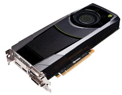
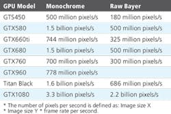
In the past, JPEG image compression was performed on either host PCs or digital signal processors (DSPs). Today, with the advent of graphics processors such as the TITAN and GEFORCE series of graphics processors from NVIDIA (Santa Clara, CA, USA;www.nvidia.com) that contain hundreds of processor cores, image compression can be performed much faster (Figure 1). Using the company's Compute Unified Device Architecture (CUDA), developers can now use an application programming interface (API) to build image compression applications using C/C++.
Because CUDA provides a software abstraction of the GPUs underlying hardware and the baseline JPEG compression standard can be somewhat parallelized, the baseline JPEG compression process can be split into threads that act as individual programs, working in the same memory space and executing concurrently.
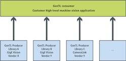
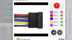
Before an image can be compressed, however, it must be transferred to the CPU's host memory and then to the GPU memory. To capture image data, standards such as GenICam from the European Machine Vision Association (EMVA; Barcelona, Spain;www.emva.org) provide a generic interface for GigE Vision, USB3 Vision, CoaXPress, Camera Link HS, Camera Link and 1394 DCAM-based cameras that allow such data acquisition to be easily made. When available, a GenTL Consumer interface can be used to link to the camera manufacturer's GenTL Producer (Figure 2).
Using Microsoft Windows this is provided as a Dynamic-Link Library (DLL) with a .CTI file extension. If there is no GenTL Producer, then it is usually mandatory to use the native camera or a frame grabber manufacturer's application programming interface (API) for retrieving camera data. Once captured, image data can be transferred to the GPU card's multiple Gigabyte memory using the cudaMemcpy function. An example of how this can be achieved can be found athttp://bit.ly/VSD-CUDA.
However, using the cudaMemcpy function is not the fastest method of transferring image data to the GPU memory. A higher bandwidth can be achieved between CPU memory and GPU memory by using page-locked (or "pinned") memory. Since the GPU cannot access data directly from pageable host memory because it has no control over when the host operating system may choose to move such data, when a data transfer from pageable host memory to device memory is invoked, the CUDA driver must first allocate a temporary page-locked, or "pinned", host array, copy the host data to the pinned array, and then transfer the data from the pinned array to device memory. This can be achieved by allocating pinned host memory in CUDA C/C++ (http://bit.ly/VSD-CUDA2).
There is also a third approach to overcoming the data transfer speed between the host and GPU memory. Allowing a frame grabber and the GPU to share the same system memory, eliminates the CPU memory copy to GPU memory copy time and can be achieved using NVIDIA's Direct-for-Video (DVP) technology. However, because NVIDIA DVP is not currently available for general use, BitFlow (Woburn, MA, USA;www.bitflow.com), a frame grabber manufacturer, has chosen to publish BFDVP (BitFlow Direct-for-Video Protocol), a wrapper of NVIDIA DVP, designed to enable integration of its frame grabber API with NVIDIA GPUs (http://bit.ly/VSD-BitF).
Bayer interpolation
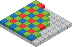
Before image compression can occur, the data from the image sensor in the camera must be correctly formatted. Most of today's color image sensors use the Bayer filter mosaic, an array of RGB color filters arranged on a grid of photosensors (Figure 3). Named after the late Bryce Bayer (1929-2012) who invented it while working for Eastman Kodak (Rochester, NY, USA;www.kodak.com), the filter uses twice as many green elements to mimic the physiology of the human eye. His idea dates to May 29, 1974 and his original handwritten concept can be found at http://bit.ly/VSD-ISW.
Since the Bayer mosaic pattern produces an array of separate R, G and B pixel data at different locations on the image sensor, a Bayer demosaicing (interpolation) algorithm must be used to generate individual red (R), green (G) and blue (B) values at each pixel location. Several methods exist to perform this interpolation including bilinear interpolation (http://bit.ly/VSD-BiLin), linear interpolation with 5x5 kernels (http://bit.ly/VSD-LinIn), adaptive-homogeneity-directed algorithms (http://bit.ly/VSD-DEM) and using directional filtering with an a posteriori decision (http://bit.ly/VSD-POST) each of which has their own quality/computational tradeoffs.
Although adaptive-homogeneity or directional filtering can be implemented on the GPU, linear interpolation with a 5x5 bi-linear Bayer interpolation on the GPU provides higher performance in high-speed video compression applications.
Such algorithms are often implemented using field programmable gate arrays (FPGAs) embedded in the camera or the frame grabber that is used to capture image data. When raw image data is captured from color cameras to host memory, Bayer interpolation can also be performed on a GPU.
After such interpolation, white balancing of the image may be required to ensure that objects which appear white are, in fact, rendered white in the resulting image (http://bit.ly/VSD-WB). This is accomplished, for instance, by computing statistics for each color in the input image and applying scaling factors so that the output image has an equal amount of each color.
Color space conversion
Color data can be reduced by transforming the RGB images into the YUV color space (or more accurately the Y'CbCr color space where Y' represents luminance and the U and V components represent chroma or color difference values. Y'CbCr values can be derived by subtracting the Y' value from the R and B components of the original image using a simple formula (http://bit.ly/VSD-FRW).
YUV supports three different conversion and subsampling modes known YUV (4:4:4), YUV (4:2:2), YUV (4:2:0) and YUV (4:1:1). Unfortunately, the notation used to describe these conversion modes is not intuitively obvious since the subsampling patterns are not described in terms of how pixels are subsampled in horizontal and vertical directions (http://bit.ly/VSD-SUB).
Generally, the YUV (4:4:4) format, which samples each YUV component equally, is not used in lossy JPEG image compression schemes since the chrominance difference channels (Cr and Cb) can be sampled at half the sample rate of the luminance without any noticeable image degradation. In YUV (4:2:2), U and V are sampled horizontally at half the rate of the luminance while in YUV (4:2:0), Cb and Cr are sub-sampled by a factor of 2 in both the vertical and horizontal directions.
Perhaps the most commonly used mode for JPEG image compression, the YUV (4:2:2) mode, can thus reduce the amount of data in the image by one-third over the original RGB image before any image compression occurs while providing little visual difference to the original image. Source code to perform this conversion in C++ can be found athttp://bit.ly/VSD-RGB.
To perform within a GPU, this color space conversion (and other functions associated with baseline JPEG compression), a knowledge of the architecture of the graphics processor is required (http://bit.ly/VSD-THR). Suffice to say that threads (the smallest sequence of programmed instructions that can be managed independently by the scheduler) are organized in blocks. These blocks are then executed by a multiprocessing unit (MPU). To perform high-speed calculations, data must be organized efficiently in memory so that the block of threads can operate autonomously. Thus, fetching data between blocks will slow performance as will the use of IF branches.
Bayer interpolation, color balancing and color space conversion can all be performed on the GPU. To perform these tasks, the image in the GPU is split into a number of blocks during which they are unpacked from 8-bit to 32-bit integer format (the native CUDA data type). For each block, pixels are organized in 32 banks of 8 pixels as this fits the shared memory architecture in the GPU. This allows 4 pixels to be fetched simultaneously by the processor cores of the GPU (stream processors) with each thread reading 4 pixels and processing one pixel at a time.
In such implementations, it can be assumed that the color balance required will be consistent over time especially if lighting conditions are controlled. By capturing a template image into host memory, a look-up-table can be created that can then be uploaded to the GPU memory to apply a scaling factor to each pixel so that the resultant image has an equal amount of each color. After this task is performed by the GPU, each pixel is converted to a 32-bit floating point value and converted to the YUV color space. Blocks are then saved to the GPU global memory.
Transforming discretely
After images are transformed from RGB to YUV color space, the JPEG algorithm is applied to each individual YUV plane (Figure 4). At the heart of the JPEG algorithm is the discrete cosine transform (DCT). This is used to transform individual 8 x 8 blocks of pixels in the image from the spatial to frequency domain. A CUDA-based version on one implementation of this algorithm can be found athttp://bit.ly/VSD-CUD-ALG.
The input to the forward discrete cosine transform (FDCT) is an array of 8 x 8 pixel blocks which, after the DCT is applied, result in a block of 8 x 8 frequency coefficients where vertical frequencies increase from left to right and horizontal frequencies increase from top to bottom. Thus, the representation of the image is concentrated in the upper left coefficients of the output matrix.
In the next step of the JPEG algorithm, quantization is used to further compress the luminance and color difference values of the frequency coefficients. Quantization tables are used to vary the amount of compression used and thus, allow output image quality to balance image quality and compressed image size. While the JPEG committee does not provide any standard quantization tables, two example tables can be found athttp://bit.ly/VSD-JPEG.
To perform this task on the GPU, the image is again split into a new set of CUDA blocks that run 64 threads (each computing a DCT) to perform a DCT on each block of the Y component of the image. After this, each pixel coefficient is converted back to 32-bit integer values and a quantization table is applied to each DCT coefficient. An explanation of how this is accomplished using CUDA can be found at:http://bit.ly/VSD-DCT. This process is then repeated for both the U and V image components, using a different quantization table for the U and V component.
After quantization, the (lower frequency) coefficients towards the top left of the 8 x 8 image matrix corner will be of higher value than those at the bottom right. To take advantage of this, before images are run-length encoded, a process known as Zig-Zag ordering is used to rearrange the coefficients in a one-dimensional order such that higher frequencies that may be represented as zero values after quantization can be encoded more efficiently.
Zig-Zag ordering
Zig-Zag ordering is applied to each of the Y, U and V components separately and two different quantization tables are used for both the Y and UV components. This information is then variable-length encoded using Huffman encoding. Again, two different encoding tables are applied to both the Y and UV components. Once again this can be implemented on the GPU (http://bit.ly/VSD-VLE).
By loading both the JPEG Luma and Chroma Huffman encoding lookup tables (LUTs) and Zig-Zag mapping LUTs to the GPU both Huffman and Zig-Zag encoding can be performed in a single step on the GPU.
By default, the JPEG compression standard defines the size of a Minimum Coding Unit (MCU) as being an 8 x 8 coefficient. By assigning these 64 coefficients to a single shared memory bank, up to 32 MCUs can be processed simultaneously.
To compute Zig-Zag ordering mapping table and run-length encoding (RLE) classification, 32 threads are used to process the 32 banks and then Huffman encoding is performed using the standard JPEG Huffman encoding lookup table. This process is repeated for each MCU block to process the Y, U and V image component planes.
Encoded data is then written to the JPEG File Interchange Format (JFIF), a format that includes the embedded encoded image data and coding and quantization tables. This packing step is not a trivial task to implement on a CPU and is typically a sequential process.
Parallelizing this function on a GPU requires a different approach. Initially, the first bit position of each MCU in the final JPEG buffer is calculated using a parallelized prefix sum algorithm (http://bit.ly/VSD-PFX). Knowing the offset position, each MCU can then be parallel pack data using the stream processors of the GPU.
After such packing, the data is then moved to the host memory for either archiving or streaming. Using the data in this JFIF image file, JPEG decoders can reconstruct the compressed image data.
Deciding on which GPU to use to implement baseline JPEG algorithms is important as compression speeds will depend on the number of multiprocessors, amount of shared memory size and number of register (Figure 5). For instance, adding more CUDA cores without increasing shared memory size or the number of registers will not increase performance. After image compression, images can be copied to the CPU's host memory or archiving or data streaming. Although the GPU-to-host memory copy time is significant, compressed image data will generally be 10-20x smaller than the original uncompressed image.
As an example, the StreamPix 7 multiple camera DVR software from NorPix (Montréal, QC, Canada;www.norpix.com), optimized for NVIDIA CUDA graphics processors can JPEG compress 3.3 billion monochrome pixels or 2 billion color pixels per second using an NVIDIA GTX1080. Using the software, capturing and compressing 12 MPixel (4096 x 3072 8-bit raw Bayer images) at 40fps from four CoaXPress (CXP) cameras simultaneously can be achieved using baseline JPEG image compression, preserving 75% image quality and allowing a 10-15x increase in image data storage compared to methods that record raw uncompressed image data.
Disclaimer
While NorPix's StreamPix 7 multiple camera DVR software uses an implementation of the baseline JPEG standard, references to code samples used in this article are for illustration purposes only. NorPix nor its affiliated companies or customers are responsible for the development or use of this code.
References
1. "CUDA Host/Device Transfers and Data Movement," by Justin McKennon for Microway (Plymouth, MA, USA;www.microway.com). Reference: http://bit.ly/VSD-CUDA.
2. "Bryce Bayer's notebook describing his RGB pattern (1974)". Courtesy of Image Sensors World (http://image-sensors-world.blogspot.co.uk). Reference:http://bit.ly/VSD-ISW
3. "Coding Bilinear Interpolation." Courtesy of The Super Computing Blog (http://supercomputingblog.com). Reference:http://bit.ly/VSD-BiLin.
4. "High-quality linear interpolation for demosaicing of Bayer-patterned color images," Henrique S. Malvar, Li-wei He, and Ross Cutler (Microsoft Research, Redmond, WA, USA;www.microsoft.com). Reference: http://bit.ly/VSD-LinIn.
5. "Adaptive homogeneity-directed demosaicing algorithm," Keigo Hirakawa and Thomas W. Parks (Cornell University, Ithaca, NY; USA;www.ece.cornell.edu). Reference: http://bit.ly/VSD-DEM.
6. "Demosaicing With Directional Filtering and a posteriori Decision," Daniele Menon, Stefano Andriani and Giancarlo Calvagno. IEEE Transactions on Image Processing Vol. 16, No.1, January 2007. Reference:http://bit.ly/VSD-POST.
7. "White balance tutorial." Courtesy of Cambridge in Colour (www.cambridgeincolour.com). Reference: http://bit.ly/VSD-WB.
8. "Framework for Video Image Compression Using CUDA and NVIDIA's GPU", Ruchi Dhore et.al. International Journal of Emerging Engineering Research and Technology (Volume 3, Issue 3, March 2015). Reference:http://bit.ly/VSD-FRW.
9. "Chrominance Subsampling in Digital Images" by Douglas A. Kerr. Reference:http://bit.ly/VSD-SUB.
10. "RGB to YUV conversion with different chroma sampling using C++." Courtesy CODE PROJECT (www.codeproject.com). Reference: http://bit.ly/VSD-RGB.
11. "CUDA-based implementation of DCT/IDCT on GPU," Xiaoming Li et.al. (University of Maryland Institute for Advanced Computer Studies; College Park, MD, USA;www.umiacs.umd.edu). Reference: http://bit.ly/VSD-CUD-ALG.
12. "Color space selection for JPEG image compression," Nathan Moroney, Rochester Institute of Technology (Rochester, NY;www.rit.edu). M.Sc. Thesis. Reference: http://bit.ly/VSD-JPEG.
13. "Parallel Variable-Length Encoding on GPGPUs," Ana Balevic, University of Stuttgart (Stuttgart, Germany,www.uni-stuttgart.de). Reference: http://bit.ly/VSD-VLE.
13. "Baseline JPEG compression juggles image quality and size," David Katz and Rick Gentile (Analog Devices, Norwood, MA, USA;www.analog.com). Reference: http://bit.ly/VSD-EE
14. "How to Optimize Data Transfers in CUDA C/C++," Mark Harris, NVIDIA Accelerated Computing Blog. Reference:http://bit.ly/VSD-CUDA2.
15. "Discrete Cosine Transform for 8x8 Blocks with CUDA," Anton Obukhov and Alexander Kharlamo, NVIDIA. Reference:http://bit.ly/VSD-DCT.
16. "NVIDIA GPU Direct," BitFlow Inc (Woburn, MA, USA). Reference:http://bit.ly/VSD-BitF.
17. "Threads and blocks and grids, oh my!" Parallel Panorama. Reference:http://bit.ly/2sDKZ9X.
Philippe Candelier, Chief Technical Officer (CTO), NorPix (Montréal, QC, Canada; www.norpix.com).
Companies and organizations mentioned
BitFlow
Woburn, MA, USA
www.bitflow.com
Eastman Kodak
Rochester, NY, USA
www.kodak.com
European Machine Vision Association (EMVA)
Barcelona, Spain
www.emva.org
International Electrotechnical Commission (IEC)
Geneva, Switzerland
www.iec.ch
International Standardization Organization (ISO)
Geneva, Switzerland
www.iso.org
Joint Photographic Experts Group (JPEG)
https://jpeg.org
NorPix
Montréal, QC, Canada
www.norpix.com
NVIDIA
Santa Clara, CA, USA
www.nvidia.com
