Lens choices abound for vision system designers
To implement cost-effective machine vision systems, developers must be aware of the numerous lens choices now available.
Andrew Wilson, European Editor
For the designer of machine vision systems, the price/performance trade off of which lens to use for a specific task is made more complex by the numerous types of lenses available, their effective resolution and image distortion characteristics.
While fixed focal lenses are still the mainstay of many machine vision systems due to their low cost, numerous other options exist including varifocal, zoom, telecentric, 360° optics and liquid lenses, each of which has their own benefits in tackling custom applications.
Determining focal length
Before any particular lens is chosen, its focal length must be determined. This choice is dependent on the required resolution of the defect being imaged, the size of the object and how far the object is from the camera. This focal length is the distance between the optical center of the lens and the image sensor of the camera.
By changing the focal length of the lens, different sized fields of view (FOVs) can be obtained. The effects of using different FOVs can be seen at:http://bit.ly/VSD-UFL. Choosing the correct focal length of a lens is dependent on the working distance of the object from the camera/lens system, the field of view required and the size of the image sensor. This is determined by the following equations:
Focal Length = (Magnification)*(Working Distance)/(1+Magnification), where Magnification = (Sensor size)/(FOV)
Thus, larger sensors will yield a larger FOV for the same working distance. As an example, the Opal-2000 camera from Adimec (Eindhoven, The Netherlands;www.adimec.com) has a sensor size of 2/3in. For an FOV of 50mm (horizontal) and a working distance of 200mm, the estimated focal length of the lens would be 29.93mm (http://bit.ly/VSD-Lens-Sel).
In choosing such a lens, however, the resolving power of the lens must be matched to the characteristics of the image sensor. Because of this, systems developers must carefully match both cameras and lenses.
To accomplish this, an understanding of the characteristics of the imager used in the camera must be understood. The camera's resolution depends on the pixel size of the image sensor, and can be calculated in line-pairs/mm (lp/mm) as: 1000 (lp/mm)/2 x pixel size (μm). Thus, for the camera's based on the CMV20000, from CMOSIS - now AMS Sensors (Antwerp, Belgium;www.cmosis.com) with a 6.4 x 6.4 μm pixel size, the limiting sensor resolution will be 78.125 lp/mm. (see "Lens choices proliferate for developers of machine vision systems," Vision Systems Design, September, 2016; http://bit.ly/VSD-Lens-Ch.)
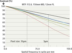
To match such a camera with a lens, developers can study the modulation transfer function (MTF) of different lenses. These provide a measurement of the lenses ability to transfer contrast at a particular resolution from the object to the image. In an example shown on the website of Edmund Optics (Barrington, NJ, USA;www.edmundoptics.com), an ICX625 sensor from Sony (Tokyo, Japan; www.sony-semicon.co.jp) with a 2/3in format and 3.45μm pixels with limiting resolution of 145 lp/mm is shown with a 12mm lens (Figure 1). Here, the maximum theoretically possible contrast that can be achieved is almost 70% at 150 lp/mm and no lens design can perform higher (http://bit.ly/VSD-MTF). Thus, choosing a high-performance megapixel camera matched to a lens with poor resolving power or an inexpensive camera with a high-performance lens will both result in low contrast images.
Fixed or varifocal?
Fixed focal lenses used in machine vision systems are prevalent since they have the benefits of using fewer optical components, low optical distortion and are relatively inexpensive. In some applications, however, the FOV may need to be modified, especially if the system design may change over time or if a systems integrator needs to determine a suitable focal length required for an application. In such cases, a varifocal length lens can be chosen. Unlike zoom lenses that maintain focus as the focal length is changed, varifocal lenses require refocusing while allowing different FOVs to be imaged.
As pointed out by Pete Kepf of CBC/Computar (Cary, NC, USA; https://computar.com) in his white paper "Seven Important Factors When Selecting a Machine Vision Lens," (http://bit.ly/VSD-7F), varifocal lenses have an adjustment that changes the magnification and FOV for a given working distance and typically have adjustments for the lens aperture, focal length and focus. Unlike fixed focal length lenses, varifocal lenses are specified across different focal lengths, for example, 3.5-8mm or 6.5-52 mm, meaning that the focal length of the lens can be can be adjusted within these ranges.
Such lenses are more expensive than fixed focal length lenses since they require a middle or rear assembly of elements that slide back and forth and a separate typically front cell focus adjustment mechanism. However, as camera vendor Lumenera (Ottawa, ON, Canada;www.lumenera) points out in "Selecting a Lens for a Vision System," if the camera used in a system has been previously selected, it may be wise to consider purchasing an inexpensive (low quality) varifocal lens to determine a suitable focal length (http://bit.ly/VSD-Sel).
Unlike varifocal lenses that require refocusing, zoom lenses or parfocal lenses maintain focus as the focal length is changed. While many companies use the term zoom lenses to describe their products, many of these are actually varifocal lenses that require manual refocussing.
For example, the MLH-3XMP lens from Moritex (San Jose, CA, USA;www.moritex.com) that features a 0.3 to 1x magnification and a working distance of 90mm, is billed as a zoom lens on the company's website. However, it is actually a varifocal lens since it features a variable focus setting. Properly named as a zoom lens, the Zoom 7000, a close-focusing manual zoom lens designed to image objects over 1in in diameter from Navitar (Rochester, NY, USA; https://navitar.com) is parfocal over its zoom range, such that captured images remain in focus over the zoom range without manually refocussing.
Zooming in
While the use of zoom lenses is less common in machine vision applications, they are used in applications such as microscopy to provide either manual or motor-controlled driven image magnification. By using such zoom lenses, systems integrators free operators of removing and replacing lenses to inspect the part at the magnification required or mounting numerous types of lenses in a turret that allow magnification to be changed without handling the lens. Using a zoom lens, the inspection system can be automated such that the system can be programmed to view a scene at low magnification and zoom in on specific details without changing lenses or rotating a lens turret (see "Understanding Optical Inspection," Quality Magazine, August 2009;http://bit.ly/VSD-UOI).
Such zoom lenses can be either manually or automatically adjusted via computer control. The design of Fetura lenses, for example, Excelitas Technologies (Waltham, MA, USA;http://www.qioptiq.com) uses two DC motors to drive both a variator lens and a compensator lens along a linear axis. While the variator lens varies the magnification factor of the image, the compensator lens compensates for the displacement of the image to bring the object being viewed into focus. (see "Zoom lenses target machine vision," Vision Systems Design, June 2008; http://bit.ly/VSD-ZOOM).
Since such lenses change their focal length by moving lens elements, this has, in the past, drawn criticism from developers requiring mechanically stable, accurate and repeatable measurements. Since their introduction in 2008, however, Excelitas Technologies has improved the design of the system in its Fetura+ making the lens system infinity corrected on both sides of the zoom, adding improved focus repeatability and optical performance around the edges of the FOV to permit compatibility with the company's Optem Fusion lens system accessories.
Telecentric designs
With conventional lenses, imaging objects nearer to the camera appear larger and those that are further away appear smaller. In high-precision gauging applications, this is detrimental since image processing software will measure the parameters of the part based on the measurements of the captured images. To overcome this, systems developers can employ telecentric lenses in which objects will appear the same size independent of their location in space.
How far an object can change its distance and still appear to be the same size is called magnification depth of field. This is different from image sharpness depth of field, which is the commonly understood meaning of depth of field (see"Using telecentric lenses in inspection systems,"Vision Systems Design, January 2005; http://bit.ly/VSD-TEL).
Telecentric lenses are generally larger and more expensive than conventional lenses due to the number of lens elements required and because the lens needs to be as large as the object being imaged. Such lenses are offered in three different variations, either as object-space, image-space, or bi-telecentric designs.
While many manufacturers offer these types of lenses, image-space telecentric lenses are more commonly used in image projection equipment and rarely in machine vision applications. In lithography systems, for example, the projection lens is typically telecentric in image-space image where lithography masks are imaged onto a silicon wafer. Such image-space telecentric lenses have the advantage that they provide a uniform light transmission across the field of view (see "Telecentric Projection Lenses in Digital Projectors," by the late Michael Pate (http://bit.ly/VSD-OSCI).
In machine vision systems, the most often used telecentric lenses are either object-side or bi-telecentric lenses. In object-side telecentric lenses, fewer lens elements are required than with bi-telecentric lenses and they are therefore less expensive.
While object-side telecentric lenses are telecentric on the object side, bi-telecentric lenses are also telecentric on the detector side, providing constant magnification even if the imager within the camera cannot be guaranteed to be always accurately positioned in the light path. Such bi-telecentric lenses are often used with collimated backlight illuminators guaranteeing high-contrast images and thus accurate image measurements.
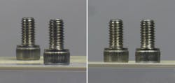
Telecentric lenses from Thorlabs (Newton, NJ, USA;www.thorlabs.com) are all bi-telecentric designs. Figure 2 shows two screws imaged with (a) the company's MVL7000 conventional lens highlighting the perspective error that would result in incorrect height measurement and (b) using the company's MVTC23013 0.128x bi-telecentric lens. Although the screws appear to be the same size and in the same object plane, they are separated by a distance of 45mm along the optical axis. As can be seen, the use of a bi-telecentric lens will result in more accurate image measurements.
Lowering camera costs
For applications in beverage, pharmaceutical and cosmetics inspection, parts must be inspected as they move along a conveyor at high-speed. To do so, it is necessary to build systems that can image both the outside, top and, often inside of the container for defects. To do so, a number of different methods exist.
Using multiple cameras positioned to image the top and sides of an object can be used to accomplish this task. Here, however, multiple cameras, mounting brackets and software calibration procedures can be used. Alternatively, the object can be rotated around the FOV of a single line scan or area scan camera to capture a 360° image. Such methods require more sophisticated mechanical engineering since the part must be stopped, rotated and inspected before a pass/fail decision is made.
To overcome this problem, pericentric or catadioptric lenses can be used. Unlike conventional lenses or telecentric lenses, pericentric lenses are designed such that the optical rays converge towards the object being imaged. Such lenses are used in machine vision systems to simultaneously view the top and sides of an object, thus reducing the number of cameras and lenses required while eliminating multiple-camera calibration complexity.
In his presentation "Panoramic inspection of objects with single lens systems," Luca Palleschi, General Manager of Opto Engineering (Houston, TX, USA:www.opto-engineering.com), shows how such single lens systems can be used to image cylindrical containers. As Palleschi admits, the size of such lenses can become large and, to reduce the size and weight of such lenses, catadioptric lenses that employ a combination of lenses and curved mirrors can be used to the same effect (Figure 3).
Electrically tunable
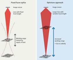
While conventional lenses can be used to image objects at different distances from the camera, should objects of different heights be presented to the imaging system, the lens will require refocussing. Although such manual adjustments can be made on automated production lines, this will require resetting the cameras for different focal lengths. One drawback to this approach is the potential increase in downtime due to the time required for changeovers. Another drawback is that this can be challenging if the camera and lens are in a difficult to access area on the equipment.
However, by using electrically-focussed tunable lenses this can be automatically accomplished in milliseconds (Figure 4). Nick Sischka, Imaging Engineer at Edmund Optics in his video presentation, "Understanding liquid lens technology," that can be found athttp://bit.ly/2wbBOi6, shows how the depth of field limitation associated with conventional lenses can be overcome using focus tunable lenses from Optotune (Dietikon, Switzerland; www.optotune.com).
While his presentation relates directly to production line environments, such electrically-focussed tunable lenses can be used in microscope-based applications, such as tracking intracellular protein complexes. Using an ix81 microscope from Olympus (Tokyo, Japan;www.olympusamerica.com), for example, and an Optotune electrically-focussed lens, a number of Z-stacked images can be imaged at high-speed (see "High-speed microscopy with an electrically tunable lens to image the dynamics of in vivo molecular complexes," Review of Scientific Instruments 86, 013707 (2015); http://bit.ly/VSD-HSM).
While currently-available lenses meet the needs of many machine vision applications, more specialized machine vision systems may demand custom lens configurations and coatings. Luckily, many well-established lens manufacturers, with in-house production capabilities are prepared to customize lenses to meet such applications. If such custom lenses or systems should be required, however, they will be more expensive and thus only found in specialized imaging systems (such as military applications) where financial considerations are not of importance or consumer products where thousands, if not hundreds of thousands of products, are produced.
Companies Mentioned
Adimec
Eindhoven, The Netherlands
www.adimec.com
AMS Sensors
Antwerp, Belgium
www.cmosis.com
CBC/Computar
Cary, NC, USA
https://computar.com
Edmund Optics
Barrington, NJ, USA
www.edmundoptics.com
Excelitas Technologies
Waltham, MA, USA
www.qioptiq.com
Lumenera
Ottawa, ON, Canada
www.lumenera
Moritex
San Jose, CA, USA
www.moritex.com
Navitar
Rochester, NY, USA
https://navitar.com
Opto Engineering
Houston, TX, USA
www.opto-engineering.com
Optotune
Dietikon, Switzerland
www.optotune.com
Olympus
Tokyo, Japan
www.olympusamerica.com
Sony
Tokyo, Japan
www.sony-semicon.co.jp
Thor Labs
Newton, NJ, USA
www.thorlabs.com


