High-speed cameras target machine vision applications
Faced with imaging high-speed events, developers can choose from those that transfer data over industry-standard camera-to-computer interfaces and stand-alone cameras.
Andrew Wilson, European Editor
Traditionally, high-speed cameras were expensive and relegated to applications such as ballistics applications and automotive testing where the cost of such systems was secondary. Today, however, with the advent of high-speed CMOS imagers, low-cost memory, high-speed camera interfaces and low-cost image capture and analysis software; high-speed cameras have found wider market acceptance in fields such as scientific research and film and video production.
CCD vs CMOS
In the late 1970s, the emergence of CCD cameras began to challenge film-based products and numerous CCD architectures including full-frame, frame-transfer and interline-transfer devices were devised to meet the demands of different applications. For high-speed imaging, the disadvantages of using CCDs included the need to employ mechanical shutters with full-frame devices, charge smearing associated with frame transfer devices and the reduction in sensitivity of interline-transfer devices due to the devices' interline mask (see "Architectures commonly used for high performance cameras," http://bit.ly/VSD-CCD, on the website of Andor Technology (Belfast, Ireland; www.andor.com).
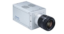
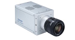
Figure 1: Optronis' CR-S3500, is a 1280 x 860 CMOS-based camera capable of running at 3,500 fps at full pixel count and specified as having an adjustable exposure time from 2μs to 1/frame rate, i.e. 2-286μs.
In the mid-1990s, CMOS-based imagers began to challenge the stronghold once commanded by CCD-based devices. These devices have several advantages over CCD-based sensors when used in high-speed camera systems, namely faster speeds and lower power consumption. They have gained acceptance in high-speed camera designs because by individually digitizing the captured charge at each photosite, blooming and smearing is eliminated and, when operated in global shutter mode, each pixel is exposured simultaneously, eliminating spatial aberrations from extremely fast-moving objects. Such global shutter modes are, however, achieved at the cost of a significantly reduced frame rate over that of operation in rolling shutter mode (see "Rolling Shutter vs. Global Shutter," http://bit.ly/VSD-SHUT, on the website of QImaging (Surrey, BC, Canada; qimaging.com).
Image motion
Knowing the exposure times of a high-speed camera is very important since this, along with the velocity of the moving part, the number of pixels in the image sensor and the camera's field of view (FOV) can have a dramatic impact on the pixel blur that occurs when an image is captured. Needless to say, to make accurate image measurements, the less this pixel blur is, the more accurate the data analysis.
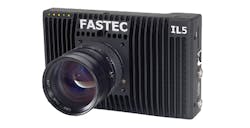
Figure 2: The IL5, a 2560 x 2048 CMOS-based camera from Fastec Imaging with a maximum frame rate of 253 fps at full pixel count can be operated in a number of windowing modes. The fastest of these windows the imager to 64 x 32 pixels allowing a frame rate of 29,090 fps to be achieved.
As Perry West, President of Automated Vision Systems (San Jose, CA, USA; www.autovis.com) points out in his excellent paper "High Speed Real-Time Machine Vision," http://bit.ly/VSD-HS, the magnitude of the pixel blur can be mathematically described as: B = (Vp x Te x Np)/FOV where Vp is the velocity of the moving part, Te is the exposure time in seconds, Np is the number of pixels spanning the view and FOV is the field of view. Thus, for a part moving at 30cm/s across a 1280 pixel imager over a camera FOV of 1000cm, an exposure time of 33ms (0.033s) would result in a pixel blur of 1.26 pixels. Even a one pixel blur such as this, Perry suggests, may become an issue in sub-pixel precision applications but one that can be resolved by decreasing the exposure time of the camera. Unfortunately, for those choosing a high-speed camera, many manufacturers do not specify the exposure times that can be achieved, merely specifying the frame rate of the camera. Indeed, some even state that the exposure time achievable is the reciprocal of the frame rate (which it may be in some cases).
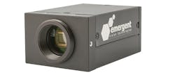
Figure 3: Emergent Vision Technologies HR-2000 is a CMOS-based camera capable of running 2048 x 1088-pixel images at 338 fps. In windowing mode, this can be reduced to 320 x 240 to achieve a 1471 fps rate. With a bandwidth of 10Gbits/s, images can be transferred to a PC without requiring host camera memory.
Frame rate relates to how many frames are captured each second and shutter speed specifies how long each individual frame is exposed (which can vary). For a graphical explanation of frame rate and exposure, see "Shutter Speed vs Frame Rate," http://bit.ly/VSD-SSFR. Thus, companies such as Optronis (Kehl, Germany; www.optronis.com) in its CR-S3500, a 1280 x 860 CMOS-based camera capable of running at 3,500 fps at full pixel count, is specified as having an adjustable exposure time from 2μs to 1/frame rate, i.e. 2-286μs (Figure 1).
Regions of interest
Unlike CCD sensors that, in partial scan mode, may suppress entire lines in the vertical direction, CMOS sensors can be operated in region of interest mode (ROI) where windowed ROIs in both the horizontal and vertical directions across the sensor can reduce the image size and thus increase the readout speed.
For this reason, many manufacturers of high-speed cameras specify both the maximum frame rate and the ROI used to achieve these rates. Fastec Imaging (San Diego, CA, USA; www.fastecimaging.com), for example, in the design of its IL5, has developed a 2560 x 2048 CMOS-based camera (Figure 2) with a maximum frame rate of 253 fps at full pixel count, that can be operated in a number of windowing modes. The fastest of these windows the imager to 64 x 32 pixels allowing a frame rate of 29,090 fps to be achieved.
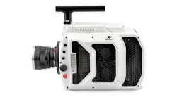
Figure 4: The Phantom V2512 camera from Vision Research is based around a custom 1280 x 800 CMOS imager that is capable of capturing 12-bit pixels at speeds of up to 25,000 fps. This equates to an image capture data rate of approximately 307Gbit/s.
With the large amount of data being captured by such cameras, systems developers need to consider whether the current camera-to-computer interfaces are enough to sustain high-speed image data transfer to a host computer. If so, then a number of high-speed interfaces are available with which to implement such systems including 10GigE, USB, CoaXPress and less-commercially popular camera-to-computer interfaces such as Thunderbolt and PCI Express. If not, then such cameras must be equipped with on-board image memory to store sequences of high-speed images that can then be later transferred to host computers for further analysis.
Two examples highlight the image transfer speeds that can be achieved with the latest camera-to-computer interfaces. Using the 10GigE interface standard, Emergent Vision Technologies (EVT; Maple Ridge, BC; Canada; www.emergentvisiontec.com), for example, offers its HR-2000, a CMOS-based camera capable of running 2048 x 1088 pixel images at 338 fps (Figure 3). In windowing mode, this can be reduced to 320 x 240 to achieve a 1471 fps rate. With a bandwidth of 10Gbits/s, this is ample enough to transfer such images to a PC without requiring host camera memory.
Similarly, in its EoSens 25CXP+ 5120 x 5120 CMOS-based camera, Mikrotron (Unterschleissheim, Germany; www.mikrotron.de) has implemented a four-channel CoaXPress implementation capable of transferring data at 25Gbits/s. In windowing mode, the 80 fps rate of the camera's full 5120 x 5120 pixel imager can be reduced to 1024 x 768, increasing the frame rate to 423 fps.
Other high-speed interfaces such as the 10Gbit/s Thunderbolt 2 and the 64Gbits/s PCIe Gen3 interfaces have been employed by Ximea (Münster, Germany;www.ximea.com) in the MT023MG-5Y and xiB-64 series of cameras respectively. Forthcoming standards such as USB 3.2 Gen 2 also promise faster data transfer rates for developers of high-speed cameras. Although companies such as FLIR Integrated Imaging Solutions (Richmond, BC, Canada; www.flir.com/mv) and others have not, at the time of writing, offered any products based on this standard, the company does offer a number of products based on the 5Gbits/s USB 3.1 Gen 1 standard and is likely to offer 10Gbit/s USB 3.2 Gen 2 cameras soon.
Going faster
While high-speed interfaces are allowing relatively high-speed data transfer between cameras and host computers, even the fastest implementations cannot be used for some of the most demanding high-speed applications. For example, the Phantom V2512 camera from Vision Research (Wayne, NJ, USA; www.phantomhighspeed.com) is based around a custom 1280 x 800 CMOS imager that is capable of capturing 12-bit pixels at speeds of up to 25,000 fps (Figure 4). This equates to an image capture data rate of approximately 307Gbit/s - faster than can be transferred from camera to host computer using any popular commercially-available camera to computer interface.
For this reason, the camera can be equipped with up to 288GBytes of memory so that at speeds of 10,000 fps, an approximately 20s image sequence can be captured. At data rates of 25Gpixels/s, over 7.6s of recording time can be achieved. Once captured, this data can be saved in the camera's 2Terrabyte CineMag IV non-volatile memory and/or downloaded to a host computer over a 10Gbit Ethernet interface.
Similarly, the Fastcam SA-Z from Photron (San Diego, CA, USA; www.photron.com) also employs a proprietary CMOS imager with 1024 x 1024 pixels capable of capturing 12-bit image data. Running at 20,000 fps, this equates to a data capture rate of approximately 250Gbit/s. This data is then captured in the camera's 128GBytes internal memory that can be transferred to an optional FASTDrive 2TByte removable SSD drive or downloaded to a host computer over a dual Gigabit Ethernet interface. Other companies, such as iX Cameras (Woburn, MA, USA; www.ix-cameras.com) also produce such high-speed cameras, all of which can run at variable frame rates based on the ROI chosen.
Responding to light
When specifying which model to choose, systems integrators must, according to Chris Robinson, Director of Technology with iX Cameras, be aware of more than just frame rates, shutter speeds, camera-to-computer interfaces and on-board image memory capability. One of these is sensitivity or how well the camera responds to light (see sidebar "Understanding ISO in a digital world," p.26 this issue).
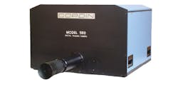
Figure 5: Cordin's rotating mirror-based camera allows twenty, forty or seventy-eight 2Mpixel CCD images to be captured at frame rates of 4 million fps.
For its part, Vision Research specifies this ISO using the ISO 12232 SAT method, for both tungsten and daylight illumination as ISO 100,000T, 32,000D when the camera is operated in monochrome mode. "iX Cameras specify this sensitivity as 40,000 for its i-SPEED 726 since the "D" is optional, but the "T" is not and because iX Cameras are tested in daylight, not quoting "D" after the ISO reading is correct, but sub-optimal," says Robinson.
Because camera shutter speeds are often of the order of microseconds in high-speed imaging applications, ensuring the correct amount of lighting is present is important. To increase the amount of light, many applications use strobed LED illumination. However, when deploying such lighting, systems integrators must ensure that both camera, lighting and triggering are tightly coupled to reduce system latency.
To study ballistics, for example, Dr. Chris Yates and his colleagues at Odos Imaging (Edinburgh, Scotland; www.odos-imaging.com) developed a system based on the company's SE-1000 camera. With an input latency of less than 1μs, equivalent to a bullet traveling less than 1mm across the camera's FOV, the time between trigger and exposure is short enough such that the bullet will not enter the FOV of the camera until after recording is initiated (see "High-speed vision system targets ballistics analysis," Vision Systems Design, December 2015; http://bit.ly/VSD-BALS).
Interestingly, while the origins of digital high-speed imaging stem from its film-based origins, many historically film-based standards such as the ISO sensitivity standard have migrated (albeit somewhat unsuccessfully) to the digital domain. Likewise, some of the concepts such as film-based rotating mirror cameras have been adapted using solid-sate imagers, an example of which is the Model 560 high-speed rotating mirror camera from Cordin (Salt Lake City, UT, USA; www.cordin.com) that allows twenty, forty or seventy-eight 2M pixel CCD images to be captured at frame rates of 4M fps (Figure 5).
In the future, while faster camera-to-computer interfaces will lower the cost of high-speed imaging for many applications, the use of cameras with on-board memory and novel opto-mechanical architectures will remain for those requiring even faster image capture.
Understanding ISO in a digital world
Many of those responsible for specifying high-speed cameras will realize the importance of sensitivity. Those in the machine vision industry realize that the specific sensitivity of any given camera is device specific and depends on a number of factors including the quantum efficiency, pixel size, and the shot noise and temporal dark noise associated with the CCD or CMOS imager used in the camera (see "How to Evaluate Camera Sensitivity," FLIR White Paper; http://bit.ly/VSD-CAMSEN).
For those involved in high-speed imaging, the ISO standard is often used to describe sensitivity. ISO Sensitivity (or ISO speed) is a measure of how strongly an image sensor or camera responds to light; the higher the sensitivity the less light that is required to capture a good quality image. However, the ideas and measurements behind it are less well known. If two cameras are rated at ISO 1200, will they produce the same images for the same amount of light? Regrettably, the answer is "not necessarily."
Film sensitivity measurements began in the late 1800s and, since then, many organizations have vied to produce the dominant standard. DIN and ASA ratings were the de-facto standards for many years and, in 1974, the International Standards Organisation (ISO) started collecting these together, eventually creating ISO 6, 2240 and 5800.
In 1998, as digital cameras became ubiquitous, ISO created a new standard specifically for digital still cameras. The latest version, ISO 12232-2:2006 has become the de-facto standard for digital still and video cameras. The rigorous method in the standard requires an illuminated scene, a camera to collect images and a measurement or assessment of the images. Unfortunately, there are options in each of these steps.
For example, the standard allows the use of either daylight or tungsten lighting. For a monochrome camera, especially one without an IR-cut filter, tungsten illumination is advantageous. This is supposed to be declared with a "T", such as ISO 1200T. However, the use of a "D" for daylight is optional, so the compulsory "T" could be lost without being noticed.
Also, illumination in the test can be measured at the scene as either a "scene luminance method" or at the sensor as a "focal plane method." The mathematics in the standard should yield the same value for both techniques, but there is a temptation to try them both to see if one gives better results.
The biggest discrepancies come from the choice of image rating technique. There are two noise-based speed measurements, Snoise10 and Snoise40, which are related to film standards. There is also the saturation-based speed measurement, Ssat, but this method does not prevent manufacturers from using an undisclosed amount of gain. The concept of recommended Exposure Index (EI) correctly allows for gain in the camera, but this is closely related to another measurement, the Standard Output Sensitivity whose result does not mention gain. In truth, gain is not necessarily bad, but it will increase noise in an image, which may prove more undesirable than lower sensitivity.
The differences between Saturation-based and Standard Output Sensitivity are documented in "ISO Sensitivity and Exposure Index," - Technical Documentation from Imatest (Boulder, CO, USA; www.imatest.com) that can be found at http://bit.ly/VSD-IMA.
Choosing a camera would be easier if all manufacturers were to use the same measurement - perhaps an update to the standard would be beneficial. In the meantime, the saturation method, with true disclosure of gain and light source technology would seem to be a good baseline.
Chris Robinson, Director of Technology, iX Cameras (Woburn, MA, USA; www.ix-cameras.com)
Companies mentioned
Andor Technology
Belfast, Ireland
www.andor.com
Automated Vision Systems
San Jose, CA, USA
www.autovis.com
Cordin
Salt Lake City, UT, USA
www.cordin.com
Emergent Vision Technologies (EVT)
Maple Ridge, BC, Canada
www.emergentvisiontec.com
Fastec Imaging
San Diego, CA, USA
www.fastecimaging.com
FLIR Integrated Imaging Solutions
Richmond, BC, Canada
www.flir.com/mv
iX Cameras
Woburn, MA, USA
www.ix-cameras.com
Mikrotron
Unterschleissheim, Germany
www.mikrotron.de
Odos Imaging
Edinburgh, Scotland
www.odos-imaging.com
Optronis
Kehl, Germany
www.optronis.com
Photron
San Diego, CA, USA
www.photron.com
QImaging
Surrey, BC, Canada
www.qimaging.com
Vision Research
Wayne, NJ, USA
www.phantomhighspeed.com
Ximea
Münster, Germany
www.ximea.com
For more information about high-speed camera companies and products, visit Vision Systems Design's Buyer's Guide buyersguide.vision-systems.com
