Understanding image-filtering algorithms
Understanding image-filtering algorithms
Peter Eggleston
Software image filtering is the process of modifying an image to block or pass a particular set of frequency components. When related to sound, communication, and transmission, the term "frequency" is readily understood by engineers. To rationalize the patterns in images as frequency components, however, is often harder for engineers to conceptualize. In imaging, filtering is most often used to enhance the spatial or geometric patterns caused by the intensity of light, rather than the frequency of light.
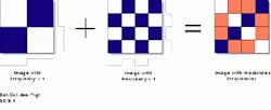
For instance, in Fig. 1, a series of checkerboard patterns is used to illustrate various square waves of differing frequencies. For each square wave, frequency is calculated as C/X, where C is the number of cycles within the X space interval. This approach is actually the operational basis for the Hadamard transform, in which an image is transformed into a representative series of square-wave functions. In contrast, a Fourier transform uses sine waves as a basis or sampling function.
Based on the understanding that an image comprises a collection of frequency components, the next step is to determine how image filtering can implement imaging functions that pass, filter, boost, or suppress various frequencies. The objective of image filtering is to locate the desired information of interest in certain parts of the frequency spectrum or to remove undesirable frequencies.
Low-pass filtering is useful in smoothing an image. It is often accomplished by applying a basic convolution operator that is widely used in signal and image processing. This linear operator performs a shift, multiply, and integrate function. In linear processes, an orderly set of processing steps is performed in an identical manner on every pixel in an image. In contrast, nonlinear operators contain decision logic that often branches out into suboperations or which contain processing that is conditional on the data parameters.
In Fig. 2, an image-processing kernel whose elements are all equal to "1s" is convolved with an original image; the resulting "averaging" effect suppresses the high-frequency information in the image. As a result, the low-frequency information passes through unchanged. Low-pass filtering is often used to eliminate spurious artifacts in an image caused by noise picked up during the image-acquisition process. From an engineering standpoint, what is often called low-pass filtering is in essence high-stop filtering; that is, both the low- and mid-frequency components are passed, while the high-frequency components are suppressed.
In removing the high-frequency components contained in an image, important imaging information, such as edges, is smoothed or lost entirely. A nonlinear imaging process called median filtering is, therefore, the preferred choice for removing noise while maintaining edge quality. Median filtering, which is a nonlinear process, is better considered as belonging to a class of enhancement operators. It is similar to low-pass filtering, but, while the averaging operation forces uniformity, the median filter allows the majority of pixel values to rule. That is, in averaging, a very high- or low-pixel intensity can greatly skew the results of the convolution operation, forcing values outside the norm for the surrounding neighborhood of pixels.
Median filtering is much less sensitive to the effect of these "outliers," as it rank-orders the intensity and then picks a middle intensity to represent its neighborhood of pixels. It can eliminate noise spikes in images while preserving the edges, but it will round the corners on objects as well as eliminate very fine lines.
Band-pass filtering is useful when it is desirable to retain only a certain range of intermediate frequencies in an image, while blocking both the high and low frequencies. This type of filtering is useful because certain image features appear as peaks in intermediate frequencies. Another use of band-pass filtering is to remove pattern noise, which could result during the digitization or transmission processes. In this case, the band-pass filtered image would be subtracted from the original image to remove or suppress the pattern noise.
Band-pass filtering is most often implemented via Fourier-transform filtering. In this filtering process, an image is first translated from a geometric representation (x, y) to a frequency-component representation. In the case of a Fourier transform, the image is represented by a series of sine waves of various frequencies and phases. Once transformed, the frequency representation is modified by attenuating or boosting certain frequencies. Then, the inverse transform is computed to create the resulting filtered image. This Fourier processing technique is often used to implement filters that would otherwise involve the use of large convolution kernels, as it involves less computation.
High-pass filtering is used to enhance rapidly changing areas of the image most often associated with the edges of the image. A variety of convolution techniques is associated with edge enhancement and will be covered in detail in a future column.
Another type of filter, a low-stop filter, is often labeled as a high-pass filter. A low-stop filter suppresses rather than boosts the low-frequency information in an image, and can therefore reduce the effects of uneven lighting or shading (see Fig. 3). Low-stop filtering can be implemented by either Fourier-transform filtering or pyramid filtering; it results in passing the mid- and high-frequency components of an image.
Another filtering operator, called an image pyramid, is a hierarchical multiresolution representation of the data in an image. It consists of a pyramid of levels, each smaller by a factor of two from the one below (see Fig. 4). Each level is produced by the same computation, such as an averaging function. In this example, the various levels in the pyramid represent the effects that would be obtained if convolution kernels of various sizes were used to average the original image. Because averaging reduces the high-frequency content of an image, the images in the pyramid become low-pass filtered versions of the original image. The further up the pyramid levels the filtering process moves, the more high-frequency information it removes. Creating a filtered image the same size as the original image calls for an interpolation process. In this process, new pixels are created by inferring them from adjacent values.
Consider again the low-stop filtering process. If an image contains only very-low-frequency components and these components are subtracted from the original image, then the effects of uneven lighting in the image will be suppressed or stopped.
All the described filtering techniques can be used in isolation to enhance the viewing quality of images, or they can be used as processing steps to derive better results from subsequent processing steps. For instance, in Fig. 3, low-stop filtering ensures that all the elements of the processing grid are segmented via thresholding. In this process, the pixels that possess a lower-than-threshold intensity are set to "0"; those pixels at or above the threshold intensity are set to "1."
Filtering techniques are available as part of most entry-level image-processing software packages. Professional-level toolkits contain at least the rudimentary filtering algorithms. Next month`s column will investigate a variety of enhancement operators, many of which are based on the discussed filtering techniques.
PETER EGGLESTON is North American sales director, Imaging Products Division, Amerinex Applied Imaging Inc., Amherst, MA; e-mail: [email protected].

FIGURE 1. An image can be rationalized as containing waveforms of various spatial frequencies. For instance, a series of checkerboard patterns can be used to illustrate various square waves of differing frequencies. For each square wave, frequency is calculated as C/X, where C is the number of cycles within the X space interval. In the Hadamard transform, an image is transformed into a representative series of square-wave functions. In contrast, a Fourier transform uses sine waves as a basis or sampling function.
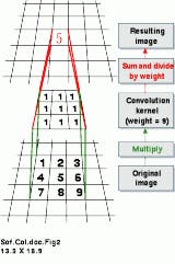
FIGURE 2. Convolution is an imaging process that implements a shift-multiply-integrate operation. During execution, the center pixel of a processing kernel is centered over a pixel in the input (old) image. The old pixel values under the processing kernel are then multiplied by the corresponding processing pixels, which, in this example, are all equal to "1." The results of all the multiplications are added together or integrated. The resulting values are written to the output image. In this example, the output (new) pixel value is equal to the average of the input image`s 3 ¥ 3 neighborhood. The processing kernel is next shifted to the adjacent pixel in the input image, and the process is repeated for that pixel. In this example, the resulting output image becomes a smoothed version of the input image.
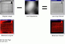
FIGURE 3. The effects of uneven lighting on an image can be removed by applying a low-stop filter operation. In this example, the low-frequency components (center) are subtracted out of the original image (left) to obtain an improved, filtered image (right). This allows for more-accurate follow-on processing such as the binarization of the image to extract the boundary of this lead-battery acid.
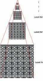
FIGURE 4. An image pyramid is a hierarchical, multi-resolution representation of an image. It is formed by successively reducing the resolution of the image by a factor of two at each pyramid level. Image pyramids correspond to a low-pass filtering operation. The lower levels of resolution correspond to losses in high-frequency information.