Understanding more mathematical morphology
Understanding more mathematical morphology
BRUNO LAŸ
Last month I introduced the concept of mathematical morphology on binary images and presented basic operators such as erosion, dilation, opening, and closing (see Vision Systems Design, May 1999, p. 27). This column extends the use of these operators to gray-scale two-dimensional (2-D) images. Although all of the concepts described here apply to 2-D images, they also can be extended to three-dimensional (3-D) and higher-dimension images.
Since the early 1980s, most research in morphology has been done on gray-scale images. For the past 10 years, however, this research has concentrated primarily on the segmentation of complex images and the extraction of moving or distortable objects in image sequences. Currently, morphology is also being used to define new compression standards such as MPEG-4.
In the late 1970s, Jean Serra, director of the Center of Mathematical Morphology, School of Mines (Paris, France), introduced the Umbra operator, which played a key role in the early formulation of gray-scale morphology. Later, Ed Dougherty, director of the imaging division of the Texas Center for Applied Technology (TX), used these functions and provided counterparts for binary translation, subset, and union. And, Luc Vincent, director of software development at Xerox Corp. (Palo Alto, CA), introduced gray-scale morphology on graphs and worked on a fast implementation of the watershed algorithm.
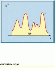
The Umbra operator is introduced to simplify the discussion of the erosion and dilation operators on gray-scale images because the concepts cannot be explained in simple terms. However, figures and images help to clarify their operation. Consider a function ƒ, which could be a 1-D signal. The Umbra of f, denoted by U(ƒ), consists of all the points lying beneath the graph of f (see Fig. 1). In mathematical notation, U(ƒ) can be defined as
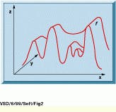
For a gray-scale image, the union of all the Umbra functions is the set of points lying below the graph of the image (see Fig. 2). The Umbra of a 2-D image is therefore in 3-D space. This set is also known as the topography of the image. In mathematical notation, U(ƒ) is defined as
The Umbra operator is useful as a mechanism for expressing gray-scale morphology in terms of binary operators. Historically, the structuring elements used with Umbrae were flat structuring elements (see Vision Systems Design, May 1999, p. 27). Since the introduction of Umbrae by Serra, 3-D volumetric structuring elements have been commonly used, as well as others defined by the total number of points in a geometric shape.
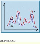
The erosion of Umbra U(ƒ) by a flat disk B is defined as a set of points (x, y) where B is totally contained in U(ƒ); see Fig. 3.
In other words, the erosion by a structuring element B is equal to
Erosion reduces the peaks of f and enlarges the valleys. On a digitized image, the computation of an erosion in a 3*3 neighborhood is equivalent to finding the minimum values within the neighborhood.
As with binary images, dilation D is the dual transformation of erosion, where the term Inf is replaced by the term Sup. Dilation fills the valleys and enlarges the peaks. The following definition is valid only for a symmetric structuring element; otherwise, the reflection of B about the origin should be considered.
Although gray-scale morphology is based on erosion and dilation, these operators are not frequently used by themselves. More commonly, they are used as suboperations for openings, closings, edge detectors, and top-hat transformations.
Gray-scale opening and closing operators have properties similar to their binary counterparts. Figures 5 through 7 illustrate the results of an opening operator applied to function f and to the gray-scale image in Fig. 5. Figures 6 and 7 illustrate an opening operator of size 3 performed on Fig. 5 and the subtraction of the original image from the result of the opening.
After the subtraction process, all the small, bright objects are present in the image, and all the large ones have disappeared. An opening process does not affect the dark areas. A threshold can then be applied to the image in Fig. 7, yielding a binary image. This sequence of operations is called a top-hat transformation, as it is based on an opening process by a flat structuring element of a given size, followed by a threshold. The threshold value H is actually the height of the top hat. Since its introduction by Meyer, group leader at the Center of Mathematical Morphology, School of Mines, in the late 1970s, this operator has been widely used in quality control and medical applications to locate defects and to extract long, thin objects such as blood vessels in an image.
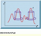
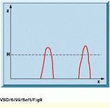
This transformation is powerful, as it can extract objects with given characteristics such as shape and defined contrast with the background, when a simple threshold would not do the job. Figure 8 illustrates the top-hat transformation on a function ƒ, and Fig. 9 depicts the final result of the top-hat transformation on the original function ƒ.
In Vision Systems Design in March 1999, Robert Belknap introduced the edge detection and gradient operators based on a linear combination of pixels in a neighborhood. Using morphological operations, it is also possible to introduce the concept of a morphological gradient (MG), which can detect the sharp edges in an image
where E is erosion and D is dilation.
The morphological gradient is equivalent to the difference between the maximum and minimum values in the same neighborhood. As with other gradients, MG can be followed by a gray-scale skeleton operator to thin the edges or by a threshold operator to obtain a binary image containing the edges. It can also be used as a marker to reconstruct objects with special characteristics such as shape or intensity.
Combining opening and closing operators with structuring elements of various sizes can lead to powerful filtering techniques, where only objects of various sizes and shapes are extracted. This type of technique is called alternate sequential filtering.
A popular gray-scale morphological algorithm used in real-world applications is the watershed algorithm. It was introduced by Lantuéjoul and Beucher, group leaders at the Center of Geostatics and Mathematical Morphology, School of Mines, in the early 1980s. Since that time, at least half of the staff of the Centre de Morphologie Mathématique (Paris, France) have been working on various software implementations, using markers to reduce oversegmentation, and on hardware implementations to accelerate the detection speed. Current research includes the use of watershed in compression techniques and in videophone, interactive CD-ROM, and Internet applications. In the past, watershed was used in classical applications such as electrophoresis gels, grain sizing, and tracking.
To simplify the explanation of a watershed operation, consider a geographical analogy. For example, contemplate that you cross a watershed line while driving from the Mississippi River to San Francisco. On the east side of the Rocky Mountains, all the rivers and streams flow into the Mississippi River. On the west side, all the rivers and streams empty into the Pacific Ocean.
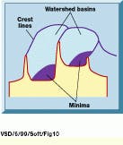
The task of segmenting an image is equivalent to finding the boundaries between regions. These regions are usually differentiated by their intensity, and if the regions are dark, the boundaries between them are brighter (see Fig. 10).
The detection of a watershed transformation in an image can be visualized by the mental concept of "water flooding." Consider the analogy that holes are punched in the minimums or image basins. The topography below the minimums is then flooded as the released "water" rises rapidly. When the "water" in the two basins attempts to merge, a high dam is built to prevent the merging. After the flooding is completed, only the tops of the two dams are visible. These tops are interpreted to define the watershed.
Noisy images tend to generate many gray-value minimums, resulting in an oversegmentation of the watershed. In such cases, software techniques exist to detect a subset of the original watershed. These techniques, using constrained minimums, are proving useful. From a real-world noisy image, a good segmentation can be obtained where only objects of interest are detected and isolated. Watershed techniques also can be used to segment stacks of convex particles of different sizes in binary images. Many different implementations of the watershed algorithm exist, based on successive thresholds, queuing techniques, and special image scanning.
Morphology theory is now a mature area of image processing. It is used to solve complex problems such as the segmentation of fuzzy images, the detection of moving vehicles on a highway, and the tracking of moving characters on a screen. Morphological algorithms are available in software packages, dedicated hardware, and specialized chips. More information about morphology is available on the Web: www.ensmp.fr; search for Research, Fontainebleau, and CMM.
FIGURE 1. Consider that function f is a one-dimensional signal. The Umbra of function ƒis therefore denoted by U(f), which is in 2-D space and consists of all the points lying beneath the graph of f in the hatched region. The Umbra can then be considered as a binary set on which binary operators such as erosion and dilation can be applied.
FIGURE 2. For a gray-scale image, the union of all Umbra functions is the set of points lying below the graph of the image. The Umbra of a 2-D image is therefore in 3-D space. This set is also known as the topography of the image and is defined as the union of all sections along the y axis.
FIGURE 3. The erosion of umbra U(f) by a flat disk B is defined as the set of points (x, y) where B is totally contained in U(f). The erosion of function ƒis shown as a dashed line.
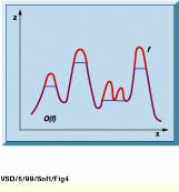
FIGURE 4. The opening of the original function f is shown in green. Note that the opening always lies beneath the original function.
FIGURE 5. An original image of several clocks is shown. The purpose of the successive operations is to detect small, bright areas such as the digits and the hour and second hands.
FIGURE 6. An opening operator of size 3 is performed on the gray-scale image of Fig. 5. Note that all the small, bright areas have been removed. However, the large oblong areas below each clock are still present.
FIGURE 7. After subtracting the image in Fig. 5 from the image in Fig. 6, all the small, bright objects are still present in the image, but all the large objects have disappeared.
FIGURE 8. In function ƒ as defined in Fig. 1, the high, narrow peaks are detected by performing a top-hat transformation, because they are the only peaks that both fit within the circumference of the hat shape and extend above it. The radius of the top hat is equal to the size of the opening operator.
FIGURE 9. After an opening process is performed on function f and then a subtraction from the original function, only the peaks detected in Fig. 8 are present. A threshold of value H is then applied, corresponding to the height of the top hat. After the threshold is performed, only the tops of the peaks and part of the binary image are detected.
FIGURE 10. In a popular gray-scale morphological algorithm, the watershed transformation, there are two minimums or valleys, and the watershed is made up of crest lines dividing two disconnected basins.
For example, when a watershed transformation is performed on an original gray-scale image of a photographer,
noise images tend to generate many gray-value minimums, resulting in an oversegmentation of the watershed.
BRUNO LAY is both president of ADCIS SA, 14200 Herouville Saint-Clair, France, and vice president of international sales and marketing at Amerinex Applied Imaging Inc., Northampton, MA; e-mail: [email protected].


