Imaging system in autonomous vehicles maps ocean turmoil
Scientists are using a compact side-scan-sonar imager carried by an underwater autonomous vehicle to study ocean-heating phenomena.
By John Haystead,Contributing Editor
Powered by lithium batteries and carrying scientific instruments and imaging sensors, vehicles with remote environmental monitoring units (REMUS) can be programmed to automatically collect acoustic Doppler current profiler (ADCP), conductivity, temperature, and depth (CTD), and side-scan-sonar data over an 80-km range traveling at 3 knots. These small, low-cost autonomous underwater vehicles (AUVs) are being developed by the Oceanographic Systems Laboratory of the Woods Hole Oceanographic Institution (Woods Hole, MA).
(CTD), and side-scan-sonar data over an 80-km range traveling at 3 knots. These small, low-cost autonomous underwater vehicles (AUVs) are being developed by the Oceanographic Systems Laboratory of the Woods Hole Oceanographic Institution (Woods Hole, MA).
Funded by the National Oceanographic and Atmospheric Administration and the National Undersea Research Program, ten REMUS vehicles have been built and deployed for a number of research applications. For example, they will play an important role in future sonar research being conducted at an ocean depth of 15 meters by the Rutgers University (New Brunswick, NJ) Long-Term Ecosystem Observatory (LEO). Located 9 km off the coast of New Jersey, two LEO-15 unmanned undersea observatories are linked to the Rutgers University Marine Field Station (Tuckerton, NJ) via electro-optical cables that provide real-time information to scientists monitoring the long-term changes in the coastal undersea environment.
RIGHT. FIGURE 1. The remote environmental monitoring units (REMUS) vehicle is powered by lithium batteries; carrying scientific instruments and imaging sensors, this autonomous underwater vehicle collects side-scan-sonar imaging data to study the "upwelling effect" in coastal areas as the summer sun heats the surface of the ocean. This heating effect combines with offshore winds to pull cold nutrient-rich water from the deep ocean to the surface along the coastline in a near cyclonic flow, which can destroy fish.
One or more REMUS vehicles will be permanently garaged at LEO-15, ready for remote launch on preprogrammed data-collection and observation missions. In tests at the facility last summer, a REMUS vehicle successfully demonstrated its ability to autonomously launch and return to its 1-m docking cone to download data, recharge its batteries, and be reprogrammed for its next mission.
For its chief mission at LEO-15, a REMUS vehicle is being used to study the "upwelling effect" that occurs annually in the NJ coastal area. As described by Christopher von Alt, principal engineer and head of the Woods Hole Oceanographic Systems Laboratory, the upwelling phenomenon occurs regularly each year as the summer sun heats the surface of the ocean. This heating effect combines with offshore winds to pull cold nutrient-rich water from the deep ocean to the surface along the coastline in a near cyclonic flow.
RIGHT. FIGURE 2. Remote environmental monitoring units (REMUS) vehicle is controlled by an onboard PC-104 computer running Microsoft Windows software. During operation, the system implements a host remote-control protocol to manage the communications between the sonar and the REMUS control computer over a bidirectional RS-232 serial link.
The nature and mechanics of the phenomenon are important to researchers and environmentalists alike as phytoplankton (microscopic plant and animal organisms) float, drift, and breed profusely in this area. However, they eventually die and sink to the ocean bottom. These movements absorb most of the oxygen from the water. The REMUS vehicle will help map the structure and progress of the upwelling effect by making long linear surveys throughout the region. It was first used in this role last summer and will be deployed again this month.
Small and versatile
The standard REMUS vehicle is 52 in. long and 7.5 in. in diameter and weighs 68 lb in air (see Fig. 1). During navigation, it uses an array of four receiving hydrophones and a transmit/ receive unit linked to a dedicated PC-104-based digital acoustic processor. This system transmits coded pings to one or more prepositioned transponders and calculates range and bearing from the returned signal data. It can use either ultrashort-baseline or long-baseline acoustic navigation depending on the type of mission.
RIGHT. FIGURE 3. For use in autonomous underwater vehicles, the Sea Scan PC-104 computer uses a Pentium II processor running Microsoft Windows software. In addition to controlling the side-scan sonar during deployments (left), the system is used after a mission to prepare reports, manipulate data, and analyze tasks (right). The sonar-processing card plugs into the computer with all power and signal transmission provided by the PC-104 bus.
The REMUS system is controlled by an onboard PC-104 computer running Microsoft Windows (see Fig. 2). The customized motherboard houses the central processing unit (CPU), eight 12-bit analog-to-digital (A/D) channels, input/output ports, power supplies, and interface circuits. A triaxial-fluxgate-heading sensor with an integral pitch-and-roll sensor provides attitude updates to the CPU at 10 Hz via an RS-232 serial link. An analog pressure sensor determines the vehicle's depth or altitude above the sea floor.
Among its scientific instruments, REMUS carries an RD Instruments (San Diego, CA) ADCP, which collects water-column current data from both above and below the vehicle; an Ocean Sensors (San Diego, CA) CTD instrument; and a light-scattering sensor to measure water turbidity and suspended particulates.
The principal imaging system aboard the REMUS is the 600-kHz, Sea-Scan PC side-scan-sonar system built by Marine Sonic Technology Ltd. (White Marsh, VA). All of the sonar image processing is performed by a single ISA card plugged into the host PC (see Fig. 3).
The system was originally developed as a towed hydrophone unit linked via cable to a desktop control computer onboard ship. However, for the space-constrained REMUS platform, the entire system including PC was redesigned to fit into a PC-104 form-factor.
Imaging package
The Sea Scan PC-104 computer uses a Pentium II processor running Microsoft Windows software. In addition to controlling the sonar during deployments, the system also can be used after a mission to prepare reports, manipulate data, and analyze tasks. The sonar-processing card plugs into the computer with all power and signal transmission provided by the PC-104 bus. During operation, the system implements a "host remote-control protocol" to manage the communications between the sonar and the REMUS control computer over a bidirectional RS-232 serial link (see Fig. 4).
RIGHT. FIGURE 4. Diagnostic software for the remote environmental monitoring units (REMUS) vehicle allows researchers to interact with its computer system via an RS-232 serial link. The software displays the status of all REMUS sensors, including compass, depth, attitude, voltage, current, thruster rpm, leak, and ground fault. It also provides for the direct download of new operational code to the vehicle and allows direct control of the vehicle via pushbuttons and sliders.
The single-card sonar posed design challenges for the AUV implementation, however. Because all of the card's processing circuits are implemented in discrete logic, the researchers had to redesign the standard 13 x 5-in. ISA card onto the 3-in.-square PC-104 form factor. In fact, the initial card used in the REMUS system was an ISA unit with the pinouts changed to operate in a PC-104 configuration. The newly designed REMUS PC-104 card is expected to be available this month.
As described by marine sonic engineer Thomas Wilcox, "With close to a thousand components on the board, we needed to push the limits of packaging technology." Wilcox says many of the devices were in fact extremely difficult to obtain although they were often listed as currently "available" from suppliers.
Though component intensive, the board's hard-wired design provides a critical benefit to AUV systems in that it consumes less than 1/100 of the power of DSP-based processing systems. As noted by Wilcox, the entire unit, together with transducers, consumes only 8 to 10 W compared to the 500-to-1000-W range of some DSP-based systems. The PC-104 version will consume less power than the current version because it is designed with lower-power components. In addition, the system's transducer components are also being redesigned to run at lower power.
Photographic imagery
The Sea-Scan PC sonar-imaging process begins at the system's two transducer modules, which are mounted externally on either side of the REMUS vehicle. As the vehicle moves forward, successive pings from the transducers illuminate narrow bands of the sea floor on each side of the vehicle perpendicular to its direction of travel. Each ping generates an individual line of image data; all the lines are later combined to form complete images.
The ping rate is automatically adjusted according to the vessel's speed, up to a maximum rate of 30 pulses/s. A key task of the host AUV computer is to provide the Sea-Scan system with speed-over-ground data in standardized NMEA0183 GPS communication protocol. These data ensure that images will be collected with the proper aspect ratio. For example, if the REMUS vessel were to slow down while the ping-rate remained constant, the same target would be pinged multiple times and appear as an elongated target in the sonar image.
The returned signals are first collected and passed through receiver preamplifier and signal-conditioning electronics located between the transducers and the processing computer. Analog signal-conditioning filters remove the frequencies outside the band of interest prior to sending them on to the sonar card for A/D conversion.
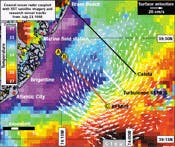
RIGHT. FIGURE 5. The tracks of REMUS missions performed last year are shown during vehicle deployment as part of the Rutgers University Long-Term Ecosystem Observatory sonar research. During the missions, the Survey REMUS AUV took sonar imaging samples along a southern cross-shelf transect between Node B and Mooring C (red line). Later, the Turbulence REMUS AUV mapped along an intermediate cross-shelf line extending from the center of the cyclonic eddy across the upwelling front (white line).
The sonar card has complete dual processing circuits for two channels, which convert signals to 8-bit data at 1.5 MHz. In addition, time-varying gain is applied to the signals to compensate for signal-strength deterioration over range.
Because range is a function of frequency, the REMUS system currently transmits at 600 kHz. This frequency allows a maximum range of 75 m/side, although it usually operates at 50 m or less to produce high-resolution images. Resolution, in turn, is a function of range. The system collects and stores a total of 1024 samples per ping or pulse, regardless of whether it is receiving from one or both data channels.
As observed by Wilcox, resolution is actually limited by the processing power of the computer, not by acoustic response. For example, at a typical 20-m range and a single channel, the resolution would be 2 cm/pixel. At 1.75 cm/pulse and theoretical acoustic resolution defined as the ability to distinguish between two side-by-side targets, the resolution would be less than 1 cm. According to Wilcox, 900- and 1200-kHz frequency capabilities are now in development with a prototype 1200-kHz system; they are providing about 40-m/side maximum range but twice the resolution.
Each sonar image "snapshot" consists of 1000-line buffer packages containing about 1.2 Mbytes of data. As explained by Wilcox, the amount of geographic area each snapshot represents is dependent on the range setting; however, it will always roughly represent a 2:1 ratio, with each snapshot being roughly twice the swath of the total area covered side-to-side. For example, at a 50-m range setting, the total swath is 100 m (both channels), and each image is about 200 m long. At this range setting, the system is expected to collect about 1 Mbyte of data every 200 m. The Sea-Scan system also includes real-time data compression that will reduce data collection to about 700 kbytes per image before storing the data on the system's small hard drive.
Although the REMUS control computer is configured to manage all the on-board sensors, depending on the mission profile, it can also be programmed to allow the sonar system to directly manage its own operation. By activating the Sea-Scan's "autogain control mode," the AUV computer can off-load these tasks, and the Sea-Scan processor then takes over control of the range, pulse rate, and gain settings.
Mapping job
The job of mapping the upwelling effect at LEO-15 requires the contributions of all the REMUS sensors. As the AUV moves through the phenomenon, the ADCP profiler maps the structure of the ocean currents in a slice above and below the vehicle, while the CTD instrument records conductivity, temperature, and depth information, which together are used to calculate ocean density (see Fig. 5).
This year, the side-scan sonar will also contribute to data collection. As pointed out by von Alt, one of the less-understood factors driving the cyclonic flow of the upwelling effect is the topographic highpoints created by sandbars that appear at regular intervals along the shore, usually associated with estuaries. With only 15 m of water between ocean surface and the top of the underwater sandbars, the REMUS vehicle will travel over the sandbar mounds to conduct detailed surface mapping using its side-scan sonar.
Because the total diameter of the upwelling effect is on the order of 20 km, the REMUS vehicle uses several signal buoys for navigation. According to von Alt, during this year, a series of 14 buoys will be deployed along the designated route, each equipped with FreeWave Technologies (Boulder, CO) broadband radio modems. The buoys will also collect temperature information and track the progress of the REMUS vehicle during the mission. To record the development of the upwelling phenomenon, the REMUS vehicle will cover 40 km/day, four times a week for three weeks.
According to von Alt, improvements and additions are planned or proposed for REMUS, including the video plankton recorder (see "Vehicle-mounted counter lets scientists study plankton," p.28) and other conventional imaging systems. The number of commercial applications for REMUS and other UAVs appears unlimited, but as pointed out by von Alt, many researchers remain skeptical about the reliability and capabilities of these platforms. "To date, the approach to UAVs has generally been to build large (36 ft long, 30-in. diameter), complex systems. These systems have often proven to be difficult to launch and recover and are also expensive ($2 million to $3 million)," he notes.
The REMUS vehicle, in contrast, is a proven, low-cost system. Without sensors, a REMUS platform costs around $70,000. Says von Alt, "In the world of deep-ocean research, this [relative cost] is just about considered expendable."
Vehicle-mounted counter lets scientists study plankton
A new imaging sensor proposed for development and deployment on a remote environmental monitoring units (REMUS) vehicle is a video plankton recorder (VPR) that is capable of identifying and measuring the ocean's biomass. This VPR will allow scientists to better assess the quantity of plankton (microscopic plant and animal organisms) in a given area as well as how it moves about over time. Although the Woods Hole Oceanographic Institution (Woods Hole, MA) has an existing towed version, the recorder must be reduced in size to make it suitable for autonomous-underwater-vehicle (AUV) implementation.
As described by Robert Goldsborough, research engineer, Applied Ocean Physics and Engineering, Woods Hole Oceanographic Institution, the basic operational principle of the VPR is that when forward-scattered light returning from an illuminated organism is collected off-axis, it provides a fairly high contrast against the water background.
The REMUS VPR will consist of a video camera, strobe flash, control electronics, and digital video recorder. It will use a compact, industrial, NTSC, charge-coupled-device video camera and magnifying optics. It is slated to image a range of plankton and particle sizes (0.1 to 7 mm for high magnification and 1.0 to 25 mm for low magnification). A high-resolution camera might also be incorporated to image a range of sizes (0.1 to 25 mm) with a single lens setting.
Flashing synchronously at 60 Hz with the camera, the strobe lenses form the incoming light into a thin (20 mm) "sheet" that extends forward of the vehicle; the process can be envisioned as a pane of glass slicing through the water. Both the strobe and the camera are mounted to the AUV on a tuning-fork-shaped bracket with about a 30-cm separation between them that affords the camera an off-axis view of the light sheet.
Although in the existing towed system data are passed directly to a workstation for real-time analysis, the REMUS VPR will instead store its images on an onboard video recorder. Using data-compression techniques, the recorder will store four hours of video on a 4-Gbyte hard disk at a compression rate of 50 to 1.
The effects of wavelet compression on VPR data were tested using a demonstration board from Analog Devices (Norwood, MA) containing the AD601 compression/decompression chip, which according to Goldsborough gave promising results. "The analysis system could select individual plankton at compression rates as high as 100 to one. But at 150 to one, the images had noticeable loss of high-frequency details," he says. In the future, Goldsborough says, the goal is to process the images in real time using an onboard DSP processor.
Company Information
Analog Devices
Norwood, MA 02062
(781) 329-4700
Web: www.analog.com
FreeWave Technologies Inc.
Boulder, CO 80301
(303) 444-3862
Fax: (303) 786-9948
Web: www.freewave.com
Marine Sonic Technology Ltd.
White Marsh, VA 23183
(804) 693-9602
Fax: (804) 693-6785
Web: www.marinesonic.com
Ocean Sensors
San Diego, CA 92117
(619) 274-9893
Fax: (619) 274-9895
Web: www.oceansensors.com
RD Instruments
San Diego, CA 92131
(619) 693-1178
Fax: (619) 695-1459
Web: www.rdinstruments.com
Rutgers University
Coastal Ocean Observation Laboratory
New Brunswick, NJ 08903
(908) 932-6555
Web: marine.rutgers.edu/mrs/lab.html