Camera Link eases frame-grabber interfacing
By Andrew Wilson,Editor
In the past, the burden of interfacing high-speed digital and analog cameras to computer-based systems was on camera vendors, frame-grabber suppliers, and systems integrators. Because of the disparate nature of camera outputs, these interfaces were often custom-built using bulky custom cabling. To effectively develop machine-vision systems, integrators needed to specify specific cameras and frame grabbers to meet their design goals.
Last year, a consortium of companies, led by Pulnix America Inc. (Sunnyvale, CA; www.pulnix. com), developed a standard interface called Camera Link to alleviate these design problems. Having a standard cable connection decreases the time needed to integrate cameras and frame grabbers. Moreover, off-the-shelf cables can be manufactured in high volumes, making the coupling of systems easier. This leads to reduced systems-integration costs because shorter interfacing time and lower-cost components are needed.
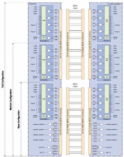
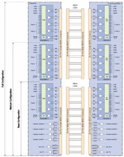
PARALLEL TO SERIALUsing a parallel-to-serial transmitter at the camera and a serial-to-parallel receiver at the frame grabber, the Camera Link standard is based on the low-voltage differential signaling (LVDS) Channel Link chipset from National Semiconductor (Santa Clara, CA; www. national.com; see Fig. 1). The implementation of Camera Link involves the use of several transmitters and receivers and additional RS-644 drivers and receivers. Most frame- grabber board vendors have chosen to implement 66-MHz DS90CR285/286 transmitters and receivers to multiplex 28 bits of data into four channels of multiplexed data. Although some companies, such as Datacube Inc. (Danvers, MA), are using the faster 85-MHz DS90CR288 parts for this purpose, most are using the 66-MHz chipset.While the Channel Link chipset provides a 28-bit data path from the camera to the frame grabber, four of the bits are used to send Frame Valid (FVAL), Line Valid (LVAL), and Data Valid (DVAL) enable signals from the camera to the frame grabber. For controlling the camera with signals such as external trigger and for serial communication with the camera, additional RS-644 drivers and receivers are used. Designated camera-control lines CC1 through CC4 are not defined by the Camera Link standard, but many camera vendors are choosing the CC1 pair for external trigger functions.
BASE, MEDIUM, AND FULLBecause a single Channel Link chip is limited to 28 bits of digital data (including four control lines), a number of devices are required to transfer data efficiently between cameras and frame grabbers. Currently, the Camera Link specification is offered in three modes: Base, Medium, and Full. The Base configuration uses one Channel Link transmitter/receiver pair to transmit data over a 26-pin Micro Delta Ribbon (MDR) connector and cable from the 3M Interconnect Solutions Division (Austin, TX). This connector allows transmission of up to 24 bits of data or different monochrome configurations.In the Medium configuration, two Channel Link transmitter/receiver pairs are used with the LVDS pairs for camera control and serial communication. In this configuration, up to 48 bits of data can be transmitted from the camera to the frame grabber. However, this transmission requires the use of two 26-pin MDR cables and connectors. The Full configuration uses another set of transmitter/receivers to transmit a theoretical 72 bits of video data.
"Interestingly," says Joseph Sgro, chief executive officer of Alacron Inc. (Nashua, NH), "while the physical interface of the Camera Link standard has been defined, bit ordering varies depending on which type of camera is used." In the Base configuration, for example, a three-tap, 8-bit/pixel color camera uses Ports A, B, and C to transmit eight bits over each color channel. A monochrome two-tap, 12-bit camera requires only 24 bits of data to be transmitted. This is accomplished by using eight bits from Port A and four bits from Port B for the first tap and four bits from Port B and eight bits from Port C for the second tap. Alternatively, a two-tap, 10-bit camera can divide bits from Ports A, B, and C to transmit 20-bit data.
These bit assignments have been designated to support a number of different camera configurations, ranging from one-, two-, or three-tap cameras at eight bits/pixel to 24-bit RGB data for the Base configuration to eight-tap cameras at eight bits/pixel for the Full Camera Link specification. These specifications are described in the Camera Link Technology Brief (DD000601) available from Basler Vision Technologies (Exton, PA; www.basler-vc.com).
Although, theoretically, 84 bits of data can be transmitted and received across any Camera Link interface, in practice, the final eight bits in the Full configuration (Port I) are not detailed in the specification. Therefore, in the Full configuration, a maximum of eight taps of eight bits/pixel or 64 bits of image data can be transmitted. "Since no one builds a nine-tap digital camera," explains Mark Butler, product manager at Dalsa (Waterloo, Ontario, Canada; www.dalsa.com), "there is no need to specify the last eight bits of the Camera Link Full specification. Furthermore," he adds, "using a Full-configuration Camera Link interface with eight 8-bit tap cameras running at 85 MHz per tap would result in a data rate of 680 Mbytes/s. At present, few companies have built cameras that run at these speeds."
According to Paul Stanton, president of Alacron, Basler has built a camera with 10 taps running at 66 MHz that provides a 660-Mbyte/s data channel to its Photobit-based 1280 x 1024-pixel camera. "But this camera is very difficult to interface as the data rate outstrips most frame-grabbers' capabilities," he says. "In addition, the camera does not adhere to the Camera Link specification because of its 80 bits of data."
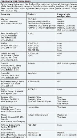
At last year's Vision East in Boston, only two vendors had announced Camera Link-compatible products. To date, more than ten frame-grabber vendors offer PCI-based Camera Link-compatible boards in a range of Base, Medium, and Full configurations (see table on p. 38). Better still, a number of camera vendors, including Adimec (Gold Canyon, AZ; www.adimec.com), Basler, Dalsa, JAI (Laguna Hills, CA; www.jai.com), and Pulnix are supporting the standard with Camera Link-compatible products.
Many Base configurations are currently offered by both camera and frame-grabber vendors. These include cameras such as the Adimec 1000M, Basler MVC series, Dalsa P2-21-06k40-00E and P2-21-08k40-00E Series, JAI CV-M4CL, and Pulnix TM 1020, TM1300, TMC6700, and TMC1000. One Base-configuration Camera Link PCI-board that supports all these cameras is the Road Runner CL from BitFlow (Woburn, MA).
"Since the release of the Road Runner CL," says Bill Carson, BitFlow director of sales and marketing, "BitFlow has validated a number of cameras with the board. And, because Camera Link eliminates proprietary cable design and manufacturing, we can focus on other aspects of the customer's application. At present, the Road Runner CL supports one camera per board, but future products will provide support for the Medium Camera Link configuration," he says (see Fig. 2).
While Dalsa's linescan cameras offer multiple resolutions, they are also offered with a number of taps. The 6k-pixel Piranha2 camera, for example, is available in both dual- and quad-output configurations with a data rate of 40 MHz per output. Dalsa's Mark Butler explains, "While the dual-tap version of the camera is supported by the Base Camera Link configuration, the four outputs of the quad-output version must be supported by the Medium configuration. Whether eight or ten bits of image data are transferred with the dual-tap version, a Base-configuration frame grabber can be used. When eight or ten bits of image data are output from the four-tap version, a Medium-configuration Camera Link board must be used," he adds.
Recognizing the need to support higher data rates, Alacron has introduced several Medium-configuration Camera Link interfaces to its range of FastVision and FastFrame frame grabbers and image-processing boards. With two Camera Link inputs, the boards can support either one Medium-, one Full-, or up to two Base-configuration cameras. "To support this number of configurations," says Alacron's Sgro, each frame grabber uses an on-board Xilinx (San Jose, CA; www.xilinx.com) field-programmable gate array (FPGA) to byte-order and synchronize the data."
Other vendors also are supporting the Camera Link standard with Medium-configuration offerings. The microEnable board of Silicon Software (Mannheim, Germany), for example, offers a single Medium-configuration or two independent Base-configuration cameras (see Fig. 3). "In the microEnable-II camera, we will develop a Full-configuration implementation but the required sub-board is not produced yet," says Klaus-Henning Noffz.
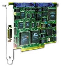
FULL THROTTLEIn the Full Camera Link configuration, a maximum of eight taps at 8 bits per tap or 64 bits of image data can be transmitted and received between a camera and frame grabber. At present, only frame grabbers from Engineering Design Team (EDT; Beaverton, OR), Coreco Imaging (St. Laurent, Quebec, Canada), and Datacube claim to support this level of imaging. But, unlike Base or Medium Camera Link implementations, the boards currently offered at the high end differ radically in their designs.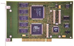
EDT's Camera Link Digital Interface board, for example, is a PCI-based half-card that uses two MDR 26 connectors to accommodate two Base, one Medium, and one Full Camera Link camera. Incorporating an on-board dual-channel DMA interface, the board is claimed to be capable of transferring data at a rate of 180 Mbytes/s using a 66-MHz PCI bus and at a rate of 117 Mbytes/s in a 33-MHz slot.
According to the company, a number of cameras are already supported by the board. These include the Dalsa Piranha2, the Illunis (Minnetonka, MN; www.illunus.com) HR3020, and the Pulnix TM-1020-15CL and TMC-6700-CL. The board also interfaces to the Silicon Imaging (Clifton Park, NY; www.siliconimaging. com) SI3170, claimed to be the world's first 3.17 million-pixel, high-definition CMOS all-digital camera capable of running at video rates of 30 frames/s at its full 2056 x 1560-pixel resolution.
Coreco Imaging's 32-bit, 33-MHz PCI interface board Viper-CamLink also supports digital cameras with up to eight 8-bit taps. Based on Camera Link, the board can be operated in Base, Medium, and Full configurations. The Full configuration permits data acquisition from eight 8-bit tap or four 10-, 12-, or 16-bit tap area- and linescan monochrome cameras and 8-, 10-, or 12-bit RGB digital-output cameras. According to Phil Colet, Coreco vice president of sales and marketing, the board has been tested with a number of Base Camera Link cameras.
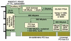
In many very-high-performance applications, however, the Camera Link interface is limited by the speed of the Channel Link transmitter/receivers used. In most currently available implementations, the Full Camera Link configuration interfaces use the 66-MHz DS90CR285/286 chipset. To increase this speed, Datacube has used the 85-MHz DS90CR287/288 chipset in the design of its Revolution PCI-based Camera Link board that support all Camera Link configurations (see Fig. 4).
Announced at Vision East in Boston this October, the Datacube 64-bit/66-MHz PCI board can simultaneously capture data from eight 8-bit taps as fast as 85 MHz/tap. This capability produces a cumulative data rate of 680 Mbytes/s. According to Ari Berman, chief technology officer at Datacube, the company has created a library of image-processing algorithms so that data once captured can be processed by a Xilinx on-board Dataflow XC2X1000 gate array.
By allowing this library of image-processing functions to be downloaded into the gate array, reconfigurable image-processing systems can take advantage of the parallel FPGA processing functions. And, because the clock rate of the Channel Link chipset used in the design is also user-programmable, the board can be interfaced to nearly every off-the-shelf line- or area-scan Camera Link camera currently available. At present, Datacube is looking at qualifying Camera Link cameras from Basler, Dalsa, Hitachi America (Westwood, MA; www.hitachidisplays.com), Illunis, JAI, Panasonic (Secaucus, NJ; www.panasonic.com/mv), Pulnix, and Silicon Imaging. "All these cameras are Base-configuration types, except the Piranha 2 from Dalsa, which is a Medium-configuration camera," adds Berman.
DUAL BASE MODEBoards that implement the Full Camera Link standard can theoretically support two Base, one Medium, or one Full Camera Link configuration. "In practice, however, even with the Full configuration, it is not possible to interface two Base-configuration cameras to the board," says Adrien Poly, international linescan sales manager at i2S Line Scan (Pessac, France). To do so would require using Transmitter 1 for the first camera and Transmitter 2 for the second camera. Because the data and the clocks are multiplexed by 7:1, this setup would result in a transmitted clock speed of 462 MHz (using 66-MHz transceivers) and 595 MHz (using 85-MHz parts).Such clock rates must be synchronized even over the length of the 10-m Camera Link cable," says Alacron's Stanton. "In Alacron's Fast Image 1300 board design, this is accomplished by placing first-in, first-out (FIFO) buffers in the data path of the board's on-board FPGA. This absorbs the skew created by the cables and restores the sync of the original data," he says. On the Fast Image 1300, two independent Full Camera link interfaces are provided with separate camera controls and serial interfaces. Already, the company has interfaced two Adimec1025 cameras to the board. The Dalsa 4M30 camera that provides four taps at 12 bits can be interfaced to the board using the two Base interfaces to implement the Medium interface. In this way, both dual Base and Medium configurations are supported by one board.
To overcome the limitation of using two cameras in the Full configuration, both i2S and Datacube are developing dual Base configurations of the standard. "Since two Channel Link transceivers are used in this double-Base configuration," says i2S's Poly, "it is more efficient than the Medium configuration because two linescan cameras can be interfaced to a single board."
Datacube's Berman agrees. "In such a dual Base configuration," he says, "the Revolution board will support two Base-configuration Camera Link cameras for the same price as the Full configuration."
Whereas the Camera Link standard does alleviate the problems of camera-to-computer connectivity, it is still not a plug-and-play interface. Although many camera vendors are using Camera Link to reduce the cabling needed, their line-scan, time-delay integration, and area-array cameras are far from standard. The byte-ordering, or tap-reversal, function is generally performed in hardware on the frame-grabber board using camera configuration files. Despite this, many vendors have endorsed the Camera Link standard. Other frame-grabber vendors, such as Data Translation (Marlboro, MA; www.datx. com) and MuTech Corp. (Billerica, MA; www.mutech.com), are readying Camera Link-type products.
Alacron's Stanton sees other problems. "There are still are too many wires, and the cable lengths are too short," he says. "In addition, special wire is needed to provide less than a 1-ns skew between the wires in the cable. What the world needs is a 5-Gbit serial optical interface."