Laser-based scanners help create 3-D models

Laser-based scanners and surface-modeling software combine to capture data points that can mathematically model a part in three dimensions.
By Andrew Wilson,Editor
Reverse engineering is a design technique in which product developers use available drawings, specifications, and physical items to produce their own copy of an established part. In the past, the process of reverse engineering three-dimensional (3-D) objects was performed by obtaining manual measurements of the original parts with mechanical coordinate-measuring machines (CMMs). These machines can produce 3-D models of parts when a technician logs the position of a probe at specific points on the part.
Unfortunately, such machines do not capture enough data points, and developers are confronted with difficult problems when determining the entire data structure of 3-D parts. Moreover, because the shape of curved surfaces cannot be documented, technicians can obtain only critical dimensions such as the location of hole centers, the diameter of holes, and the thickness of walls. In practice, this approach is time-consuming, since only several thousand data points, instead of millions, can be captured over several days.
Furthermore, CMMs are limited in their accuracy. "One of our clients performed a study of the accuracy of CMMs and found that some points could be as much as 0.005 inch off," says Arthur Andersen, president of Virtual Surfaces (Mt. Prospect, IL). "Even though only a dozen or so points would normally be erroneous, they would have a significant effect on the accuracy of the resulting digital model," he adds.
Fast and accurateVirtual Surfaces required an advanced measurement tool that could capture enough data points quickly and accurately to represent a contoured surface and also have the capability to compare two surfaces. Based on these factors, Andersen decided that a laser-based-scanner system would be more effective than other methods. This system must capture millions of data points and, by using surface modeling software, superimpose scanned data on a computer-aided-design (CAD) surface model of the part. In addition, the system must be able to indicate where the physical object deviates from the original model.Virtual Surfaces decided to use the ModelMaker from Nvision (Dallas, TX). Major components of the ModelMaker system include a 3-D laser sensor, a mechanical digitizer on which the data sensor is attached, a PC, and software that extracts, displays, and manipulates the data (see Fig. 1).
Using this system, Virtual Surfaces can scan 3-D parts, models, and objects that need to be reverse-engineered. Using a point-cloud editing and surfacing program, complete nonuniform rational B-spline (NURB) surface files can be created to provide a mathematical representation of a 3-D object.
Laser triangulationModelMaker is a portable laser-scanner-based system capable of capturing the color-coded 3-D geometry of an object. Attached to a mechanical arm that moves about the object, the scanner allows a technician to capture data and edit the object's output data to standard 3-D CAD packages. The system measures 3-D data using a laser-triangulation approach.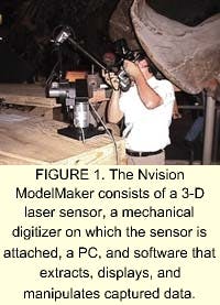
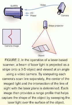
In operation, a beam of laser light is projected as a stripe onto a 3-D object and viewed at an angle with a video camera. The produced image reveals a contour of the object where the laser light intersects the surface of the object. Computing each scan line of the camera separately determines the center of the imaged light and the intersection of the line of sight with the laser plane. Each image then provides a range profile. Sweeping the light over the surface of the object aids in capturing its shape (see Fig. 2).
Laser scan data are compared to existing surface data using Surfacer, a surface-modeling program from the Imageware Division of SDRC (Milford, OH). This program creates curves and surfaces directly from scanned data, registers the scanned data, and then superimposes the data onto another surface model. Imageware Surfacer enables users to design, build, and inspect free-form-shaped products and to create free-form surfaces from curves, surfaces, or measured data.
Supporting both Bezier and NURB surface patch layouts, Surfacer's modification tools allow design changes to be explored interactively to visualize the engineering implications of a design. Complementing the suite of surface design tools are polygonal modeling and modification and basic mold design capabilities. Working with the company's I-DEAS Reverse Engineering/
Inspection Mold Manufacturing Package enables developers to generate software that can drive CNC-based machine tools.
Shape captureTo capture the shape of a part, a technician positions the laser sensor so that a line of laser light appears across the part. A mechanical digitizer, a FaroArm from Faro Technologies (Lake Mary, FL), moves about the part's body, and the associated sensor captures data. Designed for engineering, manufacturing, and controlling dimensional quality, the FaroArm delivers a measurement accuracy of ±0.0010 inch.The unit's proprietary design uses precision encoders to accurately measure the exact position of the probe tip, regardless of the user's approach to the measured part or assembly. The positional data are transferred over a serial port to the PC, where the data are associated with the 3-D camera data from the ModelMaker scanner.
As the technician moves the sensor over the surface of the part, a dedicated interface card translates the video images of the laser line into 3-D coordinates. These data are combined with the Cartesian and angular coordinates generated at each position of the mechanical arm. The result is a dense cloud of 3-D data that describes the surface of the part. Next, the data are transformed into a 3-D wire-frame model that can be imported into the Imageware Surfacer package.
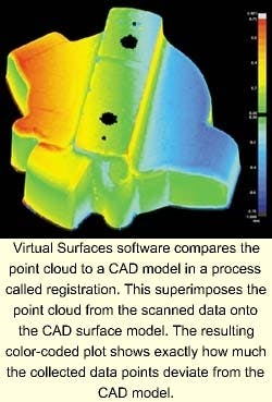
Data are also exported from the PC that runs ModelMaker into Surfacer. Here, the point cloud is compared to a CAD model in a process called registration. This process superimposes the point cloud from the scanned data onto the CAD surface model. The resulting color-coded plot shows exactly how much the collected data points deviate from the CAD model.
For example, points below the surface of the model might be shown in blue while those above the surface would be shown in red (see image on p. 45). Alternatively, all the points outside specific tolerance settings could be displayed in a single color. The software also provides statistical information about the comparison between the two data sets. For example, the software can determine the percentage of data points that are out of tolerance or provide a standard deviation value for the comparison.
Practical benefitsOne of the practical benefits of the laser-scanner/Surfacer combination is that surfaces can be copied, edited, and manipulated to make them larger or smaller or to change a feature. With Surfacer, the surfaces created from the laser scan can also be used as a guide or template for creating other surfaces.For example, Virtual Surfaces was approached by a manufacturer who had produced 100,000 parts. Unfortunately, all 100,000 parts had warped in the mold but still needed to match a second part yet to be manufactured. The design for the second mating part was already done, but since the first part was warped, the design had to be changed.
Virtual Surfaces scanned the warped part with the ModelMaker laser scanner and brought the data into Surfacer. The CAD model of the second part was imported into the system, and the two files were compared. Using the software's surface-manipulation tools, technicians adjusted the surfaces of the CAD model to match the scanned data from the physical part. The company then used the revised CAD model to make the mold for the second part.
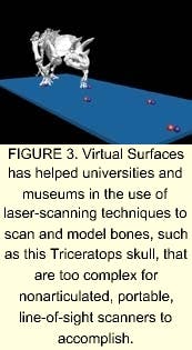
Virtual Surfaces also has worked closely with paleontologists at the University of Chicago, The Field Museum of Natural History in Chicago, and The Smithsonian Institution in Washington, DC, to help them to use these techniques for the study of fossil specimens (see Fig. 3). "A computer-aided inspection of a dinosaur leg bone is no different from that of a curved plastic part," says Andersen. "We have successfully scanned and modeled bones that were far too complex for nonarticulated, portable, line-of-sight scanners. The resulting data can be used to compare a newly discovered bone with a classified one, just as scanned part data are compared to a CAD model. In this way, the laser-scanner technology enabled paleontologists to fit specimens into the appropriate species.
"The most important use of the technology at this point, however, is helping small manufacturing companies improve the quality of their products," he adds.
Company InformationFaro TechnologiesLake Mary, FL 32746Web: www.faro.comNVision
Dallas, TX 75229
Web: www.nvision3d.com
SDRC
Milford, OH 45150
Web: www.sdrc.com
Virtual Surfaces
Mount Prospect, IL 60056
Web: www.virtualsurfaces.com