Vision system keeps trains on track
By Peter Gallon, Contributing Editor, andAndrew Wilson,Editor
In England, railroad maintenance calls for frequent inspections of wheel profiles. In the past, these inspections were made by workers either visually or using hand-held gauges. Both methods resulted in various and unreliable levels of subjective assessment. Moreover, wheel inspection failures translated into unusable vehicles, which, in turn, dramatically affected the vehicles available for service.
To overcome these problems, English railroads have installed automated vision inspection systems. These systems have stabilized scheduled wheel-inspection activities, improved measurement reliability and consistency, optimized the use of available vehicles, and identified equipment failures and maintenance trends.
Worn rails cause new wheels to quickly adopt a worn profile and vice versa. In operation, wheel/rail wear occurs slowly, with wear rates increasing slightly as the profiles become more severe. Over time, tracks and rolling stock on a railroad system reach an equilibrium. But, by closely monitoring wheel profiles, changes in the wear equilibrium and wheel shape deviations from prescribed limits can be readily detected. Wheel shape is crucial to the dynamic performance of a train as it travels around corners and to the stability of a train as it travels on straight track.
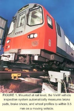
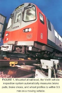
To address the inspection needs of English railroads, AEA Technology Rail (Derby, England) offers a number of automatic inspection systems to examine brake pads, blocks, shoes, and wheel profiles of rail vehicles. These systems are installed on trains or by the side of rail tracks to measure various train or infrastructure parameters (see Fig. 1). To monitor wear, brake pads, and brake blocks on steel train wheels, AEA has developed a range of vision-inspection systems called VIEW.
Placed at the end of train-wash stations, VIEW inspection systems can check train wheels and brakes every two or three days. The disadvantage of this location, however, is that moving trains drip water and acidic and alkaline solutions, and electric noise is prominent. Consequently, the vision-inspection system must be environmentally sealed. This requirement, according to Jon Pocock, AEA VIEW product manager, represented the most difficult challenge in system design.
System design
To automatically measure the profile of rail wheels, the VIEW system integrates several off-the-shelf lighting, camera, and imaging subsystems and ties them to a custom-built controller (see Fig. 2). "These subsystems enable a modular design approach to configuring a vehicle-inspection system to meet a particular customer's requirements," says Pocock. For example, AEA offers its TreadVIEW system to measure wheel profiles.
The PadVIEW and BlockVIEW modular inspection systems are tailored to measure wheel brake pads and brake blocks, respectively, usually using four cameras and four flash units (see Fig. 3). "Because the trackside computer and frame grabber can accommodate as many as 12 camera inputs, various modules can be combined to make comprehensive vision-inspection systems using only one computer," says Pocock.
To highlight the wheel shape at one point on its circumference, the train wheels are illuminated by structured lighting in the form of a divergent laser-beam light source that projects a line onto the wheel. "If a line of light is generated and then viewed obliquely, the distortions in the line can be translated into height variations," explains Pocock. "Illuminating objects with structured light and looking at the way the light structure is changed by the object provides shape information," he adds.
As part of the illumination system, a Lasiris 100-mW laser and a 670-nm bandpass filter, both from StockerYale Canada (St-Laurent, Quebec, Canada), are fitted with a beamsplitting head to produce a constantly intense diverging line. This line highlights the shape of the wheel at one point on its circumference and ensures a constant brightness across the illuminated area. The 670-nm bandpass filter removes the ambient light reflected by the polished wheels before an image is captured.
After the wheels are illuminated, they are imaged using TM9701 CCD cameras from Pulnix America Inc. (Sunnyvale, CA). Providing a resolution of 768 x 484 pixels, the camera's electronic asynchronous shutter triggers the image-capture function from the system's controller. "This method," says Pocock, "ensures that the image is taken exactly as the wheel passes by the system." The camera's internal frame store holds the captured image for readout to from one to three Pulsar frame grabbers from Matrox Imaging (Dorval, Quebec, Canada).
"In operation, the inspection system is required to grab asynchronous images from up to 12 cameras," says Pocock. "Controlling this image acquisition with software proved complicated. So a PC is used to set up the controller for initiating image grabs and lighting triggers when inputs are received from proprietary magnetic proximity devices that detect the presence of train wheels. Once an image has been acquired, the frame-grabber board downloads the images from each camera's frame store to host memory," he adds.
Image processing
After capture by the Matrox Pulsar frame-grabber board, images are analyzed using Matrox Imaging Library (MIL) software to extract wheel and other profile parameters such as flange height and flange width. All the information is then downloaded to an information display system (IDS), where it is used to build up a wear history for each wheel.
After the train has passed, the captured and processed images are saved to a file on the host PC. "Using the filtering, edge-detection, pattern-matching, pixel-manipulation, and drawing and file routines in the MIL, PadVIEW and BlockVIEW are programmed to automatically identify brake pad and brake block thicknesses," says Pocock. By analyzing the wheel images using TreadVIEW, the inspection system computes a profile of the train wheel.
In practice, Pocock discovered that when measurements were made to within ±0.5 mm in a viewing range of ±10 mm, the system could accurately determine when remedial action needed to be taken. Regular inspection using the TreadVIEW system also detects variations in the rate of change, which could bring the scheduling of remedial action forward or delay it further.
After the images are analyzed, the collected data are transmitted via a telephone link to the IDS, which carries out database management and analysis. Here, wheel profile data, for example, can be compared with known good data, and a statistical analysis can be made. The IDS uses this measurement history data to calculate current wear rates and remaining life for individual components in the train fleet.
A component change sheet can then be printed that identifies which components need to be changed.
Statistical reports showing the distribution of parameter values and wear rates by axle, vehicle unit, and train fleet can also be generated. As data builds up, a model of the problem areas within individual vehicles and across the rail fleet can be identified. In this way, historical variations in performance can be derived. Such techniques aid in rail material and resource planning.
In comparative tests with a hand-held 'Miniprof' gauge used for manually checking wheels, the TreadVIEW system has proved accurate to within 0.5 mm for checking moving vehicles. According to Pocock, this accuracy is sufficient for providing regular measurements in a cost-effective manner.
Company InformationAEA Technology RailDerby DE24 8YB, EnglandWeb: www.aeat.co.ukMatrox Imaging
Dorval, Quebec, H9P 2T4 Canada
Web: www.matrox.com/imaging
Pulnix America Inc.
Sunnyvale, CA 94089
Web: www.pulnix.com
StockerYale Canada
St-Laurent, Quebec, H4R 2K3, Canada
Web: www.lasiris.com

