X-ray imaging checks food purity
Food-inspection system uses custom x-ray sensors, image processing, and software to check 20,000 chicken pieces per hour for unwanted particles.
By Andrew Wilson,Editor
Imaging systems costing between $40,000 and $50,000 are used to inspect small food products such as baby food and candy bars and guarantee purity by detecting unwanted foreign objects such as metal particles. However, while these systems operate effectively in finding high-contrast defects in food products of high uniformity, they are less effective in finding low-contrast defects in foods such as poultry, fish, and meat.
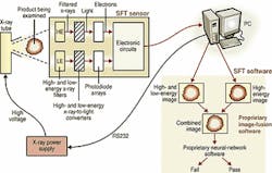
Recognizing these inspection limitations, Spectral Fusion Technologies Ltd. (SFT; Coleshill, Birmingham, England) developed an x-ray detection system to meet low-contrast food-inspection requirements (see Fig. 1). During the initial system-development phase, SFT chose a number of linear diode arrays from the former Thomson-CSF (now Thales Components Corp; Totowa, NJ) to detect x-rays as they pass though food products.
"Although they worked effectively," says Mark Graves, SFT chief executive officer, "these off-the-shelf devices had limitations. Because the photodiode arrays were temperature sensitive, they suffered from drift that results in the x-ray images appearing lighter over time—a process that had to be modeled in software. It was difficult to discriminate between a thick piece of meat without bone and a thin piece of meat with bone, since the gray scale of the resultant image could be of the same intensity," he adds.
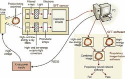
When the imaging system used a relatively low-voltage x-ray power supply of between 20 and 30 keV, it could discriminate between food bone and muscle. But at a relatively high voltage of between 40 and 50 keV, the bone and muscle absorption characteristics merged closer together (see Fig. 2). The x-ray transmission of food bone and skeletal muscle of a given thickness follows an exponential equation known as Beer's law where

null
in which the obtained intensity (I) is equal to the initial intensity applied to the food material (Io), the thickness of the material (x), and its absorption characteristic (u).
Dual energyDetermining whether a thick food material of low density or a thin food material of high density is present confronts designers of x-ray food-inspection systems with a nontrivial problem. Fortunately, dual-energy x-ray approaches can solve this problem. Already used in baggage-security and medical-imaging systems, a dual-energy approach is used in the SFT BoneScan system to discern which types of food materials, thicknesses, and densities are being imaged. During system design, a custom x-ray source and detector were developed such that the x-ray beam can be tuned to the responsivity of the detector. SFT commissioned Comet (Bern, Switzerland) to develop a custom metal-ceramic x-ray source that emits radiation between 0 and 60 keV. To power this x-ray source, SFT developed a stable power supply under PC control.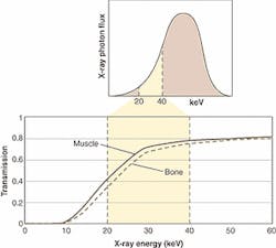
To detect the emitted x-rays after they pass through the food product being inspected, SFT designed an interface board using custom photodiode arrays. Ten 128 X 1-pixel image sensors are arranged linearly across a 25-cm viewing width (see Fig. 2). Using proprietary scintillator and filter materials, the first row of sensors blocks high-energy radiation above 40 keV, while the second row of sensors blocks low-energy radiation in the sub-20-keV range. In this manner, a process of hardware and software imaging subtraction isolates the area where the absorption characteristic of the food product differs widely.
"Before this subtraction process can occur," says Graves, "the two independent analog channels must be digitized. In the initial design, the parallel output of the photodiode array was read into a CCD sensor, where it was then serially clocked out. Unfortunately, this serial output limited the throughput and width of the imaging system since increasing the size of the photodiode array would at the same time slow the serial clocking speed," he adds.
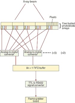
FIGURE 3. To digitize the two independent analog channels in the SFT sensor, pixel signals are read out from each of the adjacent photodiode arrays during each clock cycle. In the first clock cycle, pixel 1 is read from photodiode array 1, pixel 1 from photodiode 2, and pixel 1 from photodiode 3, and so forth. At the same time, pixel 2 is read from photodiode 1, pixel 2 from photodiode 2, and pixel 2 from photodiode 3, and so forth. In this way, all the pixels from the first array of five photodiodes are digitized and then clocked into an 8k X 1-pixel linear FIFO buffer. The second array of five photodiode arrays is clocked in a similar fashion.
To read out the pixels in the correct order from the photodiode arrays, the FIFO buffer is addressed by a complex programmable-logic-device-based state machine to rearrange the pixels into correct order before they are converted from TTL signals to standard RS-422 signals. After conversion, these pixels are read into a Snapper frame grabber from DataCell (North Billerica, MA), where two complete frames of 1024 X 1024 X 12 bits are stored. On-board the frame grabber, the two sets of images represent the energy blocked at the two x-ray energies.
"Unfortunately, a simple image subtraction does not produce the required result, as the thickness of the material and its absorption characteristic must be taken into account," says Graves. Consequently, a number of calibration experiments had to be performed on each specific type of food product. After this was accomplished, a series of nonlinear calibration curves was developed to accomplish the required result. To perform this image subtraction, SFT engineers first used the Snapper's PC-based driver to capture the images. Then, by developing user-interface and nonlinear image-subtraction software on the system PC in Microsoft C++, images could be subtracted in real time as they were captured from the imaging sensor subsystem.
Neural networksAfter the images are subtracted, the resultant image clearly shows any defects present in the product (see Fig. 4). "To determine what these defects are," says Graves, "the host-based images are fed to a custom-built multilayer-perceptron neural network with back propagation. Here again, the system must be trained to learn the subtle differences between food bone and cartilage that might still have to be removed." To properly train the system to detect the numerous types of expected food defects, an image database containing hundreds of images was developed on the host PC. "Once in place, each image could be recalled using an SFT custom-built C++ user interface, with which the user can outline the defect areas using a mouse pointer," Graves adds.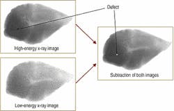
Once the database is trained, the system can inspect food products such as fish, chicken, and meat. According to SFT, the food-inspection system has been installed in more than 20 US sites.
The early systems did not use dual-energy technology. SFT has recently upgraded its inspection systems to this new technology and obtained improved performance. Current inspection systems are checking 20,000 chicken pieces per hour, and the products are guaranteed to be 99% bone-free. When a piece of chicken fails inspection, it is rejected by the PC-based motor-controlled rejection system and set aside for manual inspection.
Although these $360,000 food-inspection systems have proven successful in detecting bone fragments, manual operators still have to examine the produce pieces for cartilage. Currently, SFT is working with the Georgia Institute of Technology (Atlanta, GA) to develop a version of the food-inspection system that will detect the presence of cartilage. In this way, SFT engineers expect to produce a fully automated food-inspection system by next year.
Additional usesIn addition to offering its x-ray food-inspection system to producers of meat, poultry, and fish, SFT also expects to sell versions of its custom sensor and software to OEMs building baggage-inspection and medical-imaging systems. SFT expects its custom sensor, computer, and software combination to be used by Benthos (North Falmouth, MA), which is developing custom x-ray systems for packaged food goods using core SFT x-ray-sensing and image-analysis technology. SFT is also dealing with meat-processing companies to explore the use of x-ray technology in the robotic boning of animal carcasses. These systems would include x-ray, camera, and robotic technology.Company InformationBenthos Inc.North Falmouth, MA 02556www.benthos.comCometBern, Switzerlandwww.comet.chDataCellNorth Billerica, MA 01862www.datacell.comGeorgia Institute of TechnologyAtlanta, GA 30332www.gatech.eduSpectral Fusion Technologies Ltd.Coleshill, Birmingham B46 1JT, Englandwww.spectralft.comThales Components Corp.Totowa, NJ 07511www.tccus.com/